Nixie Calculators · Volume 7
Repair and Restoration
A Nixie calculator that has sat in a cupboard for fifty years can usually be made to work again. The tubes are tougher than their reputation, the transistors and diodes are mostly good, and the faults that do occur follow patterns that the published repair logs make clear. This volume collects those patterns: what to check before switching on, how to stay safe with the high voltages, what fails and how to find it, how to test and rejuvenate a tube, and where to find parts and documents. The best primary evidence is Brent Hilpert’s repair logs on his Early Electronic Calculators pages, which record faults and fixes in a dozen Nixie machines, and the schematics in the Library.
7.1 Safety first
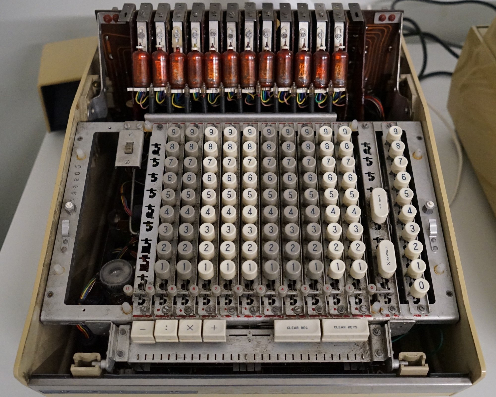
Every Nixie calculator contains voltages that can kill. The Nixie supply is typically 170 to 250 V DC, stored in reservoir capacitors that can hold their charge after the machine is unplugged. The ANITA Mk VIII is worse: its supply is about 495 V, and the heaters of its ECC81 valves are wired in series across the mains, so parts of the valve circuit sit at mains potential. The Old Calculator Web Museum declined to power its own Mk VIII.
The following is general practice for old high-voltage electronics, not advice from any calculator maker:
- Never switch on an unknown machine straight from the wall. Bring it up slowly on a variac (variable transformer), ideally through a dim-bulb tester, an incandescent lamp in series with the mains that limits the current if something is shorted.
- Check the mains voltage. Many Japanese machines are built for 100 V; a 100 V machine on 120 V runs everything about 20 % high, and on 230 V it is likely to be damaged. Check the rating plate and any voltage selector or transformer taps. The Friden EC-1115 has taps for 100, 110, 117 and 120 V.
- Discharge the high-voltage capacitors through a resistor before touching anything, and measure to confirm.
- Work one-handed near the high-voltage side, so that a shock cannot pass across the chest.
- Use an insulated screwdriver to adjust supplies. Bob Alexander, writing about his Wang 300 board, warns that its Nixie supply is 250 to 330 V.
- Beware trimmers on unregulated supplies. On the SCM Marchant 414, one trimmer turned fully the wrong way makes the output “rise sharply to the full-wave rectified mains voltage and above”, and switching off produces spikes of several tens of volts; the rails have no feedback and must be re-trimmed under load.
7.2 Before switching on
- Look inside. Look for leaking or bulging electrolytic capacitors, burnt resistors, cracked boards, broken tubes, corrosion, mouse damage and missing parts.
- Check the fuse and the power cord.
- Reseat the boards. Many Nixie calculators are built of plug-in cards, and their edge connectors are often the problem. Wang’s were not gold-plated and deteriorate; clean them gently. On the Canon 163, Hilpert warns that the boards must be inserted at an angle, with bevelled edges, or the backplane pins are crushed.
- Reform the electrolytics. Capacitors that have been unpowered for decades may have lost their oxide layer. Raising the mains voltage slowly over an hour or more on a variac lets them reform; the alternative, and on any capacitor that is leaking or bulging the only option, is replacement. Opinions differ: one Canon 130S restoration replaced all the electrolytics as routine, while a forum report found no failed electrolytics in a Sharp Compet 16 or a Casio 121, suggesting that the Japanese capacitors of the period hold up well.
- Power up slowly on the variac, watching the current and smelling for trouble, and measure the supply rails against the schematic before going further.
7.3 What fails, from the repair logs
7.3.1 Driver transistors
Leaky or shorted Nixie driver transistors are the classic display fault. A cathode driver that leaks lets a little current through an unlit cathode, which glows faintly behind the lit numeral; one that has shorted keeps its numeral lit permanently.
- In a Wang 320K keyboard, a faint “0” in every digit came from one cathode driver leaking about 120 kΩ from collector to emitter; Hilpert replaced it with an MPSA06. In another 320K, the “1” was always lit, from a collector-emitter short.
- In an IME 86S, the sixth Nixie showed ghosts; the anode driver was replaced with an MPSA92. In an IME 84, the most significant digit was dark and another dim; the anode drivers were replaced with MPSA92s.
Modern high-voltage transistors such as the MPSA42 (NPN) and MPSA92 (PNP), rated at 300 V, replace most of the original types; check the polarity and the pinout, which differ from the originals.
7.3.2 Feed-through joints
Many early Japanese circuit boards had no plated-through holes. Connections from one side of the board to the other were made with wire stubs, butt-soldered on each side, and these go open invisibly, sometimes only when warm. The symptoms are anything from no display to wrong arithmetic. Hilpert’s logs record them in a Facit 1123 (one stub had never been fully inserted, and the machine gave 2 + 2 = 8), in a Monroe 925 twice, in a Casio AL-1000’s square-root loop, and in a Toshiba BC-1212, where a bad joint on pin 7 of one chip made 5 + 5 give “8 and 2”. Canon’s boards of 1967–69 have the same problem, with poorly tinned stubs and intermittent opens that vary with temperature. The cure is to resolder every feed-through on a suspect board.
The lesson Hilpert draws is that a dead display is often not a display fault. In a multiplexed machine the display is refreshed by the same timing that runs the arithmetic, and if the clock or timing stops, the display goes dark. Look for where the clock stops before suspecting the high-voltage supply.
7.3.3 Capacitors in the display circuit
On the Toshiba BC-1212, Hilpert found that the twelve 0.022 µF capacitors in the digit drivers were rated at 200 V against a working voltage of 204 V, and replaced all twelve, along with a blown diode and an IC. Collectors report the same weakness across the Toshiba BC series: “the row of orange caps in front of the Nixie tubes”. Replace them with parts rated at 250 V or more. Any machine whose anode drive uses capacitors, such as the Friden EC-1115 described in the display volume, deserves the same check.
7.3.4 Germanium logic
The discrete germanium machines of 1964–67 suffer from open diodes and weak transistors more than from outright failures. An IME 86S restored by Hilpert in 2024 had about ten faults over a month, mostly open diodes, replaced with BAT46 Schottky diodes, and transistors replaced with 2N3906s and 2N2907s, several of them temperature-dependent. In a Canon 130S, the germanium flip-flop transistors (2SA538) were not dead but had low and widely spread gain, from 70 to 150, which gave unreliable switching; 2N3906s cured it, with 2N3904/2N3906 for the clock’s push-pull pair. Four bad diodes turned up on separate boards.
Silicon replacements work in most places, but they have a higher forward voltage than germanium. Hilpert notes that in AND gates feeding further AND gates the extra drop accumulates, and recommends Schottky diodes such as the BAT46, whose drop is close to germanium’s; the IME’s logic has enough margin, because its transistor bases are pulled well below conduction by a bias resistor.
7.3.5 The ANITA
The ANITA’s own weaknesses, according to restorers on the classiccmp mailing list:
- The high-value carbon resistors, 20 MΩ and similar, drift high with age, and the thyratrons then fail to fire reliably.
- Most of the selenium rectifier packages used as logic diodes fail. Restorers replace them with silicon diodes, potted to look like the originals.
- The gas tubes themselves “fare quite well”.
- A replacement Nixie must be the right type: “not just any Nixie tube will work” in a machine where the tubes are part of the counting circuit.
7.3.6 Delay lines
A delay-line machine (the Canon 163, Monroe 925, SOBAX 2500 and others) depends on its line. The Sony lines are potted in epoxy, and the Tech Tangents channel found one marked “unrepairable”. In the Sony 2500, where the clock is locked to the line by a phase-locked loop, a fault in the line or the loop’s charge pump stops everything; check the loop’s tuning circuit. Hilpert describes a useful trick for tracing a stuck bit in a delay-line loop: the DTL outputs have resistor pull-ups, so grounding one forces a 0 (or a 1, depending on the logic sense) into the loop, which can then be followed round with an oscilloscope. Never connect an output to the supply instead; that can destroy the chips.
7.3.7 Other faults
- Dried electrolytics. In the Wang LOCI-2 restored at the Rhode Island Computer Museum in 2020–21, a single failed electrolytic on the +10 V rail stopped everything; replacing it restored addition and subtraction. The team also found that the machine “wasn’t as broken as they thought. They had been operating it incorrectly”, and the reference manual’s examples put them right.
- Cracked boards. In one Sharp Compet 20, cracked boards had broken traces and darkened tubes.
- Keys and switches. Dirty or bent contacts: a Casio AL-1000’s program switch needed cleaning, an IME 84’s register switch needed its contacts bent, a LOCI-2 had a dead key, and an SCM Marchant 414 had contact problems in its magnetic key switches.
- Lamps. Burned-out indicator lamps can be replaced with LEDs and a series resistor; Hilpert used LEDs with 900 Ω in a Compet 17.
- Proprietary chips. House-numbered chips are often standard types: a dead 14-pin chip in a Facit 1123 proved to be a quad NAND gate, replaced with a 7400, and the Canon 163’s SN39xx and SN45xx chips match common DTL pinouts.
7.4 Symptom guide
Table 1 — Symptom guide
| Symptom | Likely cause | Check |
|---|---|---|
| Nothing at all | Fuse, power switch, transformer, supply rails | Rails at the regulator outputs |
| Display dark, machine otherwise alive (lamps work) | Nixie high-voltage supply; or clock and timing, in a multiplexed machine | HV rail; then the clock and digit counter with a scope |
| One tube dark | That tube’s anode driver or resistor (multiplexed); that tube’s decoder (static); or the tube | Swap the tube with a neighbour |
| The same numeral missing in every tube | The shared cathode line or its driver | The cathode driver for that numeral |
| A faint extra digit | Leaky cathode or anode driver; or ghosting | Measure driver leakage; check the anode timing |
| One numeral always lit | Shorted cathode driver | Collector-emitter resistance |
| Haze round every numeral | Pre-bias rail low | The bias supply |
| Dim, flickering or patchy numerals | HV low, series resistors drifted high, or worn tubes | HV rail, anode resistors, then the tube |
| Part of one numeral dark | Cathode poisoning | Rejuvenate (below) |
| Wrong answers or garbage | Feed-through joints, logic faults, delay line | Resolder; trace with the schematic |
| Intermittent faults that vary with temperature | Feed-through joints; germanium parts | Freezer spray and a hair-dryer |
7.5 Testing a Nixie tube
A Nixie is easy to test on the bench. Feed the anode from a supply of 170 to 180 V through a current-limiting resistor; 15 kΩ from about 175 V gave about 2.5 mA on an IN-12A in one hobbyist’s test. Connect each cathode to ground in turn and look at the numeral: it should be covered evenly by the glow, with no dark patches and no glow on the leads. The current can be found from the voltage across the resistor. A bench supply that can be adjusted from 140 to 200 V and limited to 10 mA is ideal.
In a multiplexed calculator a simpler test is to swap the suspect tube with its neighbour, where the tubes are socketed: the cathode lines are common, so a fault that moves with the tube is in the tube, and one that stays is in that position’s anode circuit. Most calculator tubes are soldered in with flying leads, which makes swapping a careful desoldering job. Bob Alexander’s suggestion for testing the display of a working machine is simplest of all: fill the display with all 1s, then all 2s, and so on.
A tube that will not strike at a normal voltage, or glows a diffuse purple or blue, has probably let air in through a crack or a leaking seal, and cannot be repaired.
7.6 Rejuvenating a poisoned tube
A numeral that has been unlit for thousands of hours may be poisoned: coated with sputtered metal so that it no longer glows all over. The cure, described by Dieter Wächter of tube-tester.com, is to run the poisoned cathode alone at its rated current, then raise the current gradually to two to ten times the rated maximum (the lower end for larger tubes) until the dark areas light up, and leave it to “bake” for minutes or hours. A CD47 tube’s “6” took about four hours at twice normal current.
The risks are real. If the lead-in wire at the foot of the numeral starts to glow, back off at once, or it may glow permanently at normal current. One experimenter treating IN-14s at 6–8 mA, against a rating of about 2.5 mA, found that going too fast made the leads glow, and that one digit relapsed and needed a second treatment. Dalibor Farny, who makes Nixie tubes today, found that a tube without mercury, run at five times its rated current, sputtered enough metal to short internally, while a mercury-doped tube stayed clean. Whether a given 1960s calculator tube contains mercury is not usually known. Treat calculator tubes as irreplaceable, use the low end of the range, and go slowly.
Prevention is easier. Farny recommends exercising every digit for a few minutes a day, and Bob Alexander’s modern Wang 300 board cycles every digit at midnight for the same reason. A calculator used for real calculations exercises its digits naturally.
7.7 Replacement tubes
Replacing a calculator Nixie means finding the same type, or one that matches it in size, numeral height, stacking order, decimal-point position, pinout and colour, because a mismatched tube stands out in a row. The types known in each machine are listed in the model volume and in Hilpert’s display table. Some substitutions are documented: for the Hitachi CD-81, Dieter Wächter’s data list the LD8057, CD83P and LD-946A as substitutes; for the CD-66, the CD66A and CD66P. A Rodan GR112 proved “close but not identical” to the NEC LD-866 of the Casio AL-1000. Individual tubes for the Wang 320, the National Electronics NL-843, turn up on eBay.
Soviet IN-series tubes, which are still plentiful, are not usually drop-in replacements. Their size, numeral order, decimal-point side and pinout seldom match, and calculator tubes are soldered in. A Soviet tube is a last resort, better used to replace a whole matched row than a single digit. NOS (new old stock) IN-12, IN-16 and IN-17 tubes are sold on eBay, Etsy and Tindie, often by Ukrainian sellers; “tested” is the seller’s claim. Burroughs B-5991 tubes are known to crack at the pins when pulled from sockets.
7.8 Documents
The schematics are the key to any repair. The Library holds Hilpert’s reverse-engineered schematics for the Canon 163, Sony SOBAX 2500, IME 84, IME 86S, Casio AL-1000, Casio 121-B, Sharp Compet 17, Monroe 925, Toshiba BC-1212 and Wang 320K; factory service manuals for the Wang LOCI, Friden EC-1113, Friden EC-1115 and Monroe 920; the Wang 500 schematic; and the Burroughs and Russian tube data. No service manual has been found online for the ANITA Mk VIII, the Sharp CS-10A, the Casio 001 or the SOBAX ICC-500. The Centre for Computing History in Cambridge holds folders of ANITA Mk 9, 10 and 12 circuit diagrams, not yet scanned.
7.9 Where to get help
- Brent Hilpert’s Early Electronic Calculators pages: schematics, theories of operation, logic simulations and repair logs.
- The Old Calculator Forum and neonixie-l Google Groups, and the cctalk (classiccmp) mailing list.
- The Vintage Computer Federation forum, where the LOCI-2 restoration is written up.
- John Wolff’s technical pages on the Anita 1011, Friden EC-1115, Facit 1124 and Casio AL-2000.
- The Tech Tangents YouTube channel, for the Sony SOBAX repairs.
Comments (0)