Nixie Calculators · Volume 5
Inside the Machines
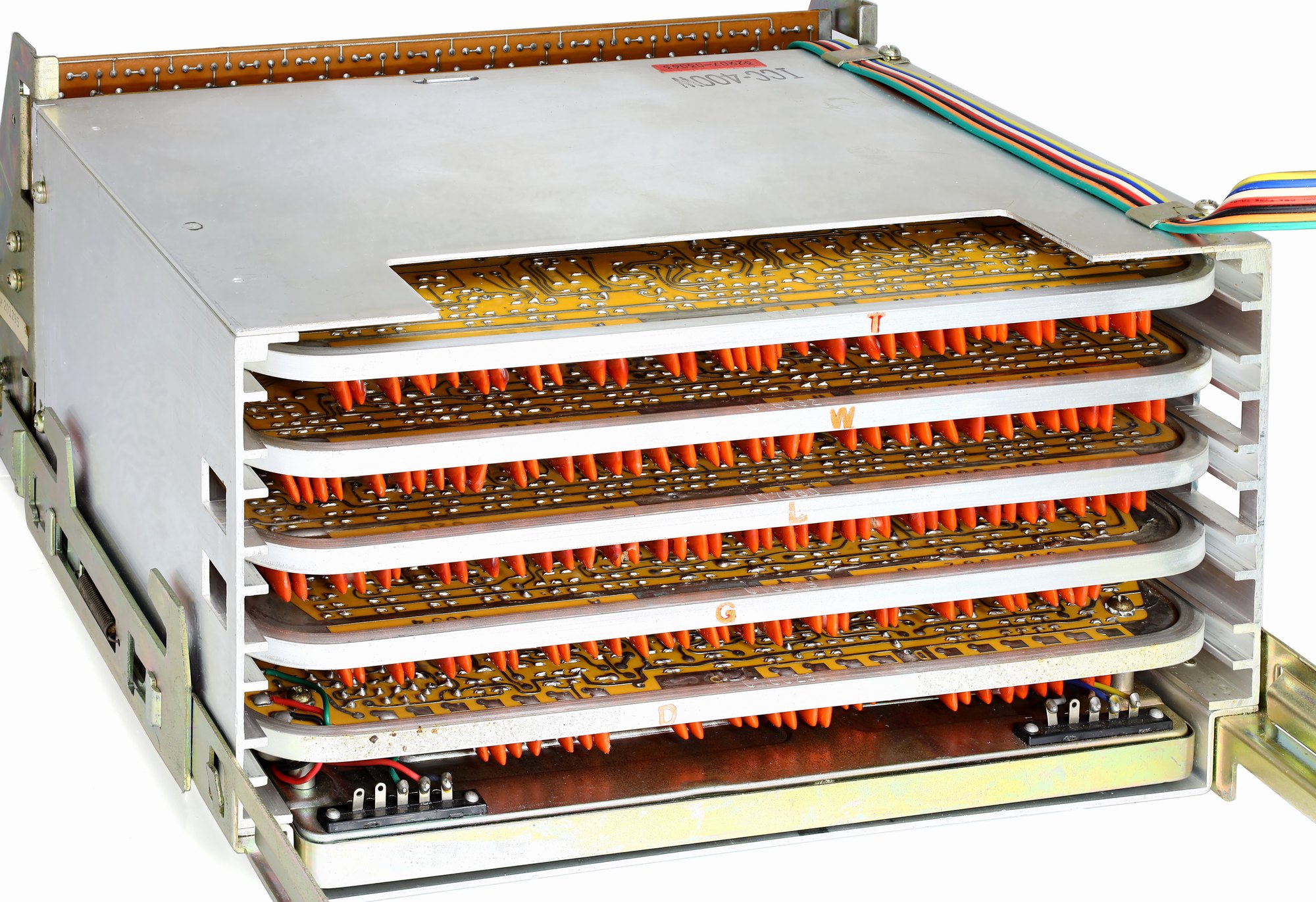
Behind the row of Nixies, the first electronic calculators were built in at least five quite different ways. The ANITA counted with gas tubes. The Sharp, Casio and Wang transistor machines kept their numbers in rows of flip-flops or in magnetic cores. The Canon, Sony and Friden integrated-circuit machines kept them circulating as sound in a coil of wire, or as charge in MOS shift registers. Toshiba stored them in capacitors. And Wang multiplied by adding logarithms. This volume describes each architecture in turn, using the patents, the factory manuals and Brent Hilpert’s reverse-engineered theories of operation in the Library.
5.1 The ANITA: arithmetic in gas
5.1.1 Cold-cathode tubes as switches
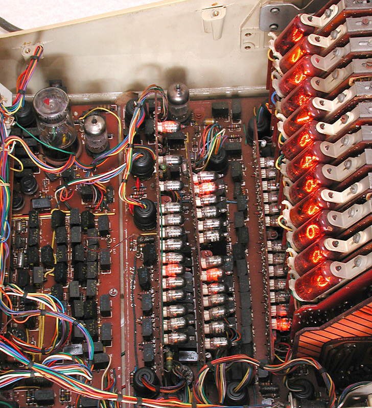
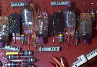
The ANITA Mk VIII has almost no transistors. Its logic is built from about 177 sub-miniature cold-cathode thyratrons, also called trigger tubes: small gas-filled tubes with an anode, a cathode and a third electrode, the trigger. Like a Nixie, a trigger tube does not conduct until the gas breaks down; unlike a Nixie, it can be made to break down at a lower anode voltage by putting a small voltage on the trigger. Once it conducts it stays conducting, whatever happens to the trigger, until its anode voltage is pulled down below the maintaining voltage. It is a gas-filled latch: it remembers one bit, and it glows when it is set, which makes the inside of a working ANITA a remarkable sight.
5.1.2 Ring counters
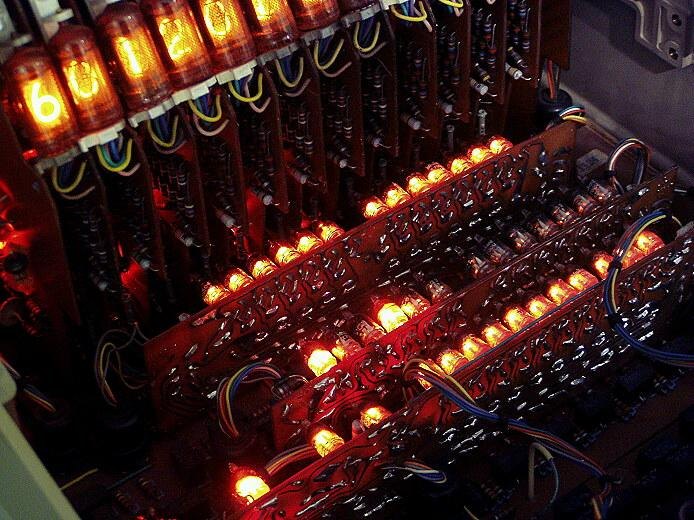
Ten trigger tubes arranged in a ring make a decimal counter. Their anodes share one resistor from the high-voltage supply, and each cathode has its own resistor to ground. Exactly one tube conducts at a time. The current through its cathode resistor raises the voltage on that cathode, and that voltage is fed to the trigger of the next tube, priming it. When a count pulse arrives on a line common to all ten triggers, only the primed tube has enough trigger voltage to fire. In the usual design, as it fires, the shared anode resistor carries the current of two tubes for a moment, the anode voltage falls below the maintaining voltage, and the tube that was conducting goes out; the new one keeps going because its own trigger is still held high. One pulse, one step; ten steps bring the glow back to 0 and send a carry to the next ring.
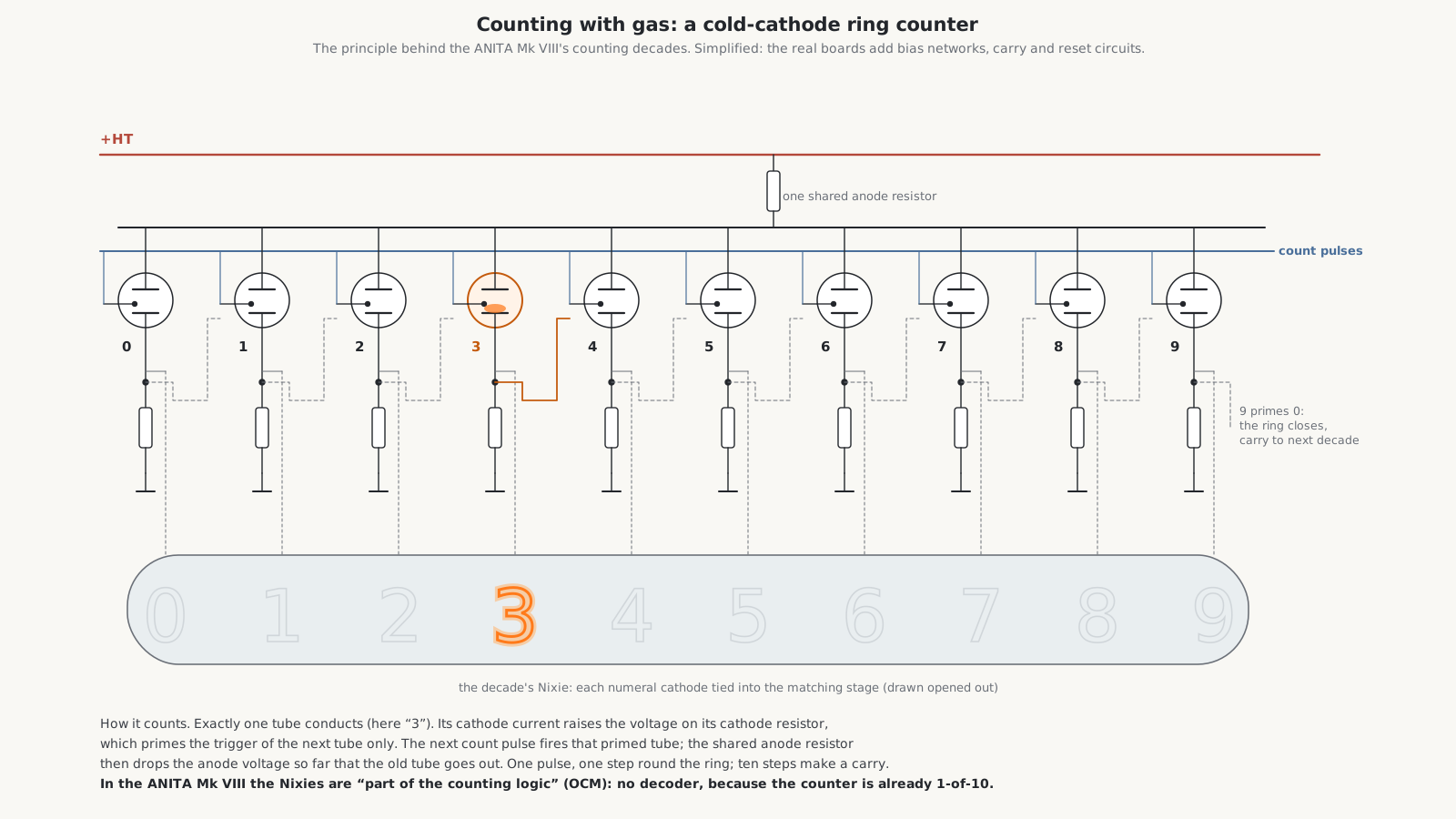
The Mk VIII has twelve such rings, 120 of its thyratrons, one ring on each of its twelve digit cards. Each ring is the register for one digit and its Nixie at the same time: the Old Calculator Web Museum describes the tubes as “part of the counting logic”, wired into the rings so that no decoder is needed. That is the elegance of the design. A binary machine has to decode four bits into one of ten numerals before it can light a Nixie; a ring of ten already is one of ten. Exactly how the Nixie cathodes are connected into the Mk VIII’s rings is not shown in any published schematic; drawing the Nixie in series with each stage’s cathode, as here, is the simplest arrangement that would work.
5.1.3 Timing and the keyboard
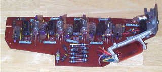
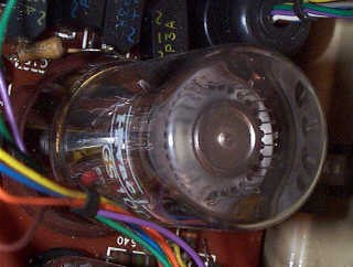
The remaining thyratrons and one Dekatron, a Hivac GS10D, provide control and timing. The Dekatron is itself a ring counter in one tube: a glow that steps round ten cathodes. In the Mk VIII it scans the keyboard, stepping from column to column, and times the operation. The master clock runs at about 3 kHz. The eleven ECC81 double triodes generate and shape the pulses that the cold-cathode tubes cannot. Logic gates are made from a couple of hundred selenium rectifiers, and the single transistor in the machine regulates the power supply.
5.1.4 What the patent describes
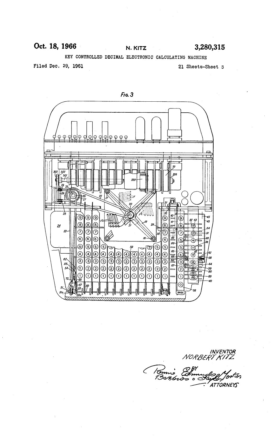
Kitz’s patent, US 3,280,315, is 59 pages long and describes two versions of the machine: an early one in which a motor-driven rotating brush scans the keys and the result is shown on mechanical numeral wheels driven from a “stepping electronic tube”, and an all-electronic version. The electronic version works as follows.
- Entry and addition. A pulse generator steps a timing device through periods T0 to T15. In period Tn, the gate for order n of the keyboard opens and passes into that order’s counting device as many pulses as the value of the key held down in that order, with carries passing into the next order up. So the machine is digit-serial in time, but every order has its own decade counter, and the counters together are the register.
- Subtraction. A switch makes each key deliver the nines complement of its value, so that an unpressed column counts 9 rather than 0, and an end-around carry completes the subtraction. The result of a subtraction that goes below zero is left as a ten’s complement, which is why the ANITA shows −1 as twelve 9s.
- Multiplication. The keyboard changes from “key-responsive” to “key-set”: the multiplicand stays held on the keys, a key in the multiplier bank sets a control device, and the machine “continues to perform repeated addition while the control device is stepped up” to the multiplier digit; then it shifts one place, multiplying by ten, for the next multiplier digit.
- Division. Repeated subtraction (adding complements) until a counter passes through 9, then “shift and complement”: the quotient digits accumulate in the low-order counters and the remainder in the high orders. The patent’s worked example is 146 ÷ 12.
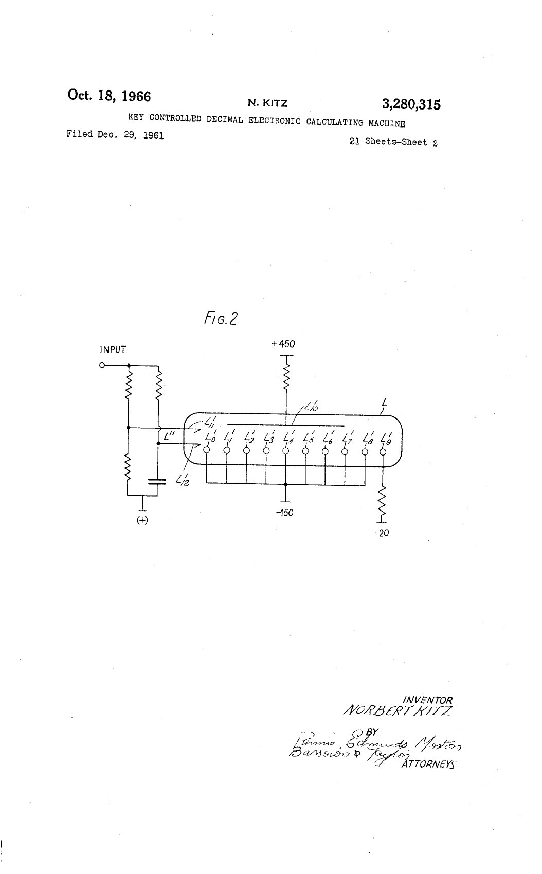
The production Mk VIII evidently replaced the brush with the Dekatron scanner and the patent’s counting devices with thyratron rings; the surviving machines and the Old Calculator Web Museum’s description agree on that, though no factory schematic of the Mk VIII has been found online.
5.2 Flip-flops and cores: the transistor machines
The Japanese and Italian machines of 1964–66 replaced the gas tubes with germanium transistors and thousands of diodes, in diode-transistor logic (DTL) or resistor-transistor logic.
The Sharp CS-10A has one plug-in card per digit and separate cards for sequencing and control. Its 530 transistors and 2,300 diodes most plausibly form parallel registers of flip-flops, with the digits processed by a shared adder; its multiplication and division times, 0.4 and 0.8 seconds, fit repeated addition and subtraction. No schematic or service manual has been published.
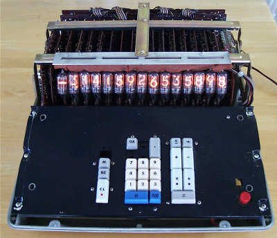
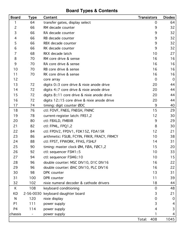
The IME 84 keeps its numbers in magnetic cores, which are cheaper per bit than flip-flops. Hilpert’s reverse-engineered theory of operation describes how it works. A free-running oscillator of about 20 kHz drives a four-step cycle that defines one digit period. In each period, one digit of each of the four main registers is read out of the core memory into a decade counter, modified if arithmetic is under way, and written back; one phase of the cycle presents a digit to its Nixie. Arithmetic is done by stretching the digit period by ten clock cycles, during which the decade counters count. A 16-state digit counter, which can count up or down, steps through the sixteen digits of a number. The board list shows how the machine is divided: five decade-counter boards and a decade latch, four core drive-and-sense boards, four boards that combine core drive with the Nixie anode drivers for four digits each, and one for the Nixie numeral decoder and cathode drivers, among 32 logic boards with 408 transistors and 1,045 diodes in all.
The Casio AL-1000 of 1967 also uses core, for both numbers and its 30-step program, in discrete DTL of more than 400 transistors and 1,500 diodes, with logic 1 at +12 V, a −6 V base bias and a +20 V core drive. A three-state ring counter sequences the reading and writing of the cores, and the display data lag the arithmetic latch by one digit time. Hilpert’s schematic is in the Library.
5.3 Wang: multiplying by adding logarithms
5.3.1 The method
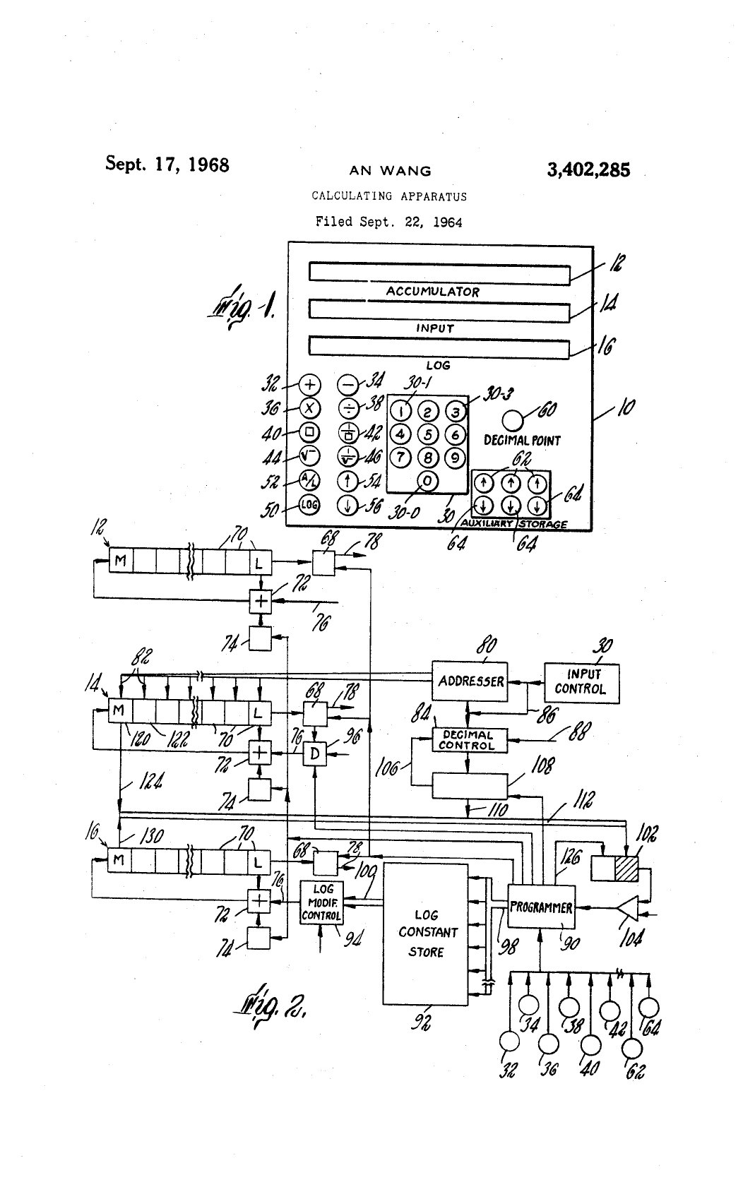
An Wang’s calculators do something no other desk calculator of the time did: they multiply by adding logarithms, as a slide rule does, but to ten digits. To multiply 2 by 3, the LOCI generates the natural logarithm of 2, adds the logarithm of 3, and takes the antilogarithm of the sum. Division subtracts logarithms; squares and square roots double and halve them; powers multiply them. The hard part is generating a logarithm quickly with simple hardware, and Wang’s US patent 3,402,285, filed in September 1964 and granted in 1968, describes how.
The machine stores the natural logarithms of a few constants: 10, 2, 0.9, 1.01, 0.999, 1.0001 and 0.99999. To find the logarithm of a number x, it repeatedly multiplies x by these constants, choosing each so as to bring x closer to 1, and keeps a running total of the logarithms of the constants used. When x has been reduced to 1, whose logarithm is 0, the running total, with its sign reversed, is the logarithm of the original x. The trick is in the choice of constants. Multiplying by 0.1 is a decimal shift. Multiplying by 2 is adding a number to itself. And every other constant is of the form 1 ± 10⁻ⁿ, so multiplying by it means adding or subtracting a copy of the number shifted n places: 0.9x is x minus x shifted one place, 1.01x is x plus x shifted two places. No multiplier is needed, only an adder and a shifter, the same hardware the machine needs for addition.
5.3.2 The patent’s example
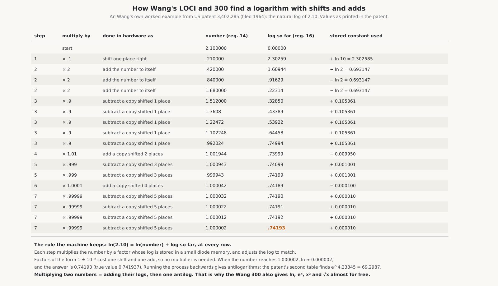
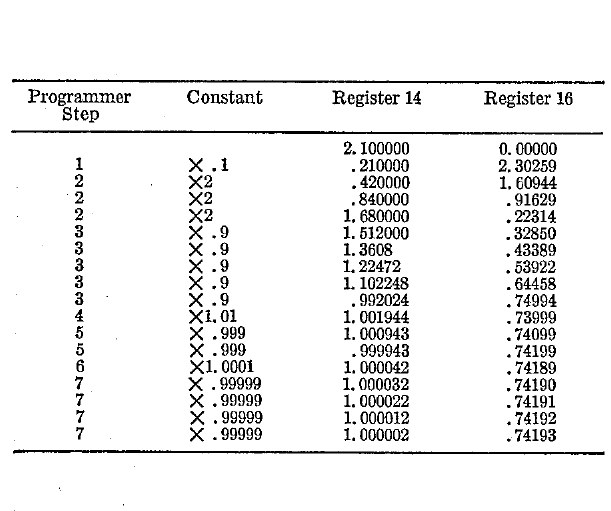
The patent works the example of ln 2.10 step by step. The number register starts at 2.100000 and the log register at 0.
- Multiply by 0.1 (shift right): the number becomes 0.210000, and the log register gains ln 10 = 2.30259.
- Multiply by 2, three times, until the leading digit is no longer zero: 0.42, 0.84, 1.68; each time subtract ln 2 = 0.69315, leaving 0.22314.
- Multiply by 0.9, five times, while the number is above 1: 1.512, 1.3608, 1.22472, 1.102248, 0.992024; each time add 0.105361 (the logarithm of 0.9 is negative, so multiplying by 0.9 means adding its magnitude). The log register reaches 0.74994.
- Multiply by 1.01 once: 1.001944; subtract 0.009950, giving 0.73999.
- Multiply by 0.999 twice: 1.000943, then 0.999943; add 0.001001 each time: 0.74199.
- Multiply by 1.0001 once: 1.000042; subtract 0.0001: 0.74189.
- Multiply by 0.99999 four times: 1.000002; add 0.00001 each time: 0.74193.
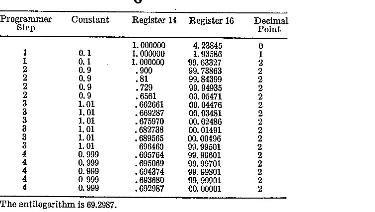
The number is now 1.000002, whose logarithm is 0.000002, and the answer is 0.74193; the true value of ln 2.1 is 0.741937. The patent notes that when the 0.99999 stage is reached, the small remaining difference between the number and 1 can simply be added to the log register, since ln(1 + ε) ≈ ε for small ε. The antilogarithm runs the same process backwards, building the number up from 1 while subtracting logarithms from the register until it reaches zero; the patent’s second table finds e^4.23845 = 69.2987 this way.
Wang’s patent says a logarithm takes under 50 milliseconds. Because every multiplication involves generating and adding logarithms, the answers carry a small error in the last place; Wang’s LOCI-2 manual warns that “each operation may introduce an error in the tenth digit, and occasionally the error may propagate to the ninth digit”. The Wang 300 works internally to 14 digits and rounds its products and quotients to 10 for display.
5.3.3 The hardware
The LOCI-2 has three working registers, W (the work register, the only one displayed), A (the accumulator, for sums) and L (the logarithm register). Each digit is four flip-flops, and with a ten-digit register needing 40 two-transistor flip-flops, the register arrays account for much of its more than 1,200 transistors. Only the storage registers are in core memory: four of them, or sixteen on the LOCI-2A. The machine runs from a −10 V unregulated supply with +6 V derived from it, and its circuit breaker is its power switch. The LOCI service manual and reference manual are in the Library.
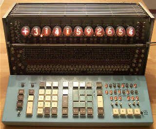
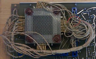
The Wang 300 electronic package, by contrast, works digit-serially on a four-bit bus and keeps its working registers in core: four registers of sixteen digits of four bits, 256 cores, of which ten digits are displayed, four are guard digits, and the rest hold the sign and the decimal position. The logic is discrete DTL on 25 small boards called Logiblocs, with logic levels of 0 and −11 V, a +11 V bias, regulated ±5.1 V supplies for the core and clock, and +250 V for the keyboards’ Nixies. The keyboards themselves contain only a diode-matrix key encoder and the display decoders and drivers.
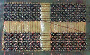
5.4 Delay lines: the Canon 163 and the Sony SOBAX
From about 1966, the Japanese makers moved to integrated circuits and to the cheapest memory of the time, the magnetostrictive delay line. A delay line is a coil of special wire a metre or more long, with a transducer at each end. A pulse of current in the write coil twists or compresses the wire by magnetostriction, and the sound wave travels down it, arriving at the read coil a little over a millisecond later. Bits are stored as the presence or absence of pulses travelling along the wire; as they arrive at the far end they are amplified, reshaped and written back in at the near end, so that the numbers circulate continuously. The memory is serial, which suits a bit-serial adder, and it holds hundreds of bits for the price of a coil of wire and two amplifiers. The sister series on CRT calculators describes delay lines in more detail.
5.4.1 The Canon 163
Brent Hilpert’s theory of operation for the Canon 163, written from a schematic he traced from two machines with parts dated 1967 to 1969, is the clearest description of a delay-line Nixie calculator available.
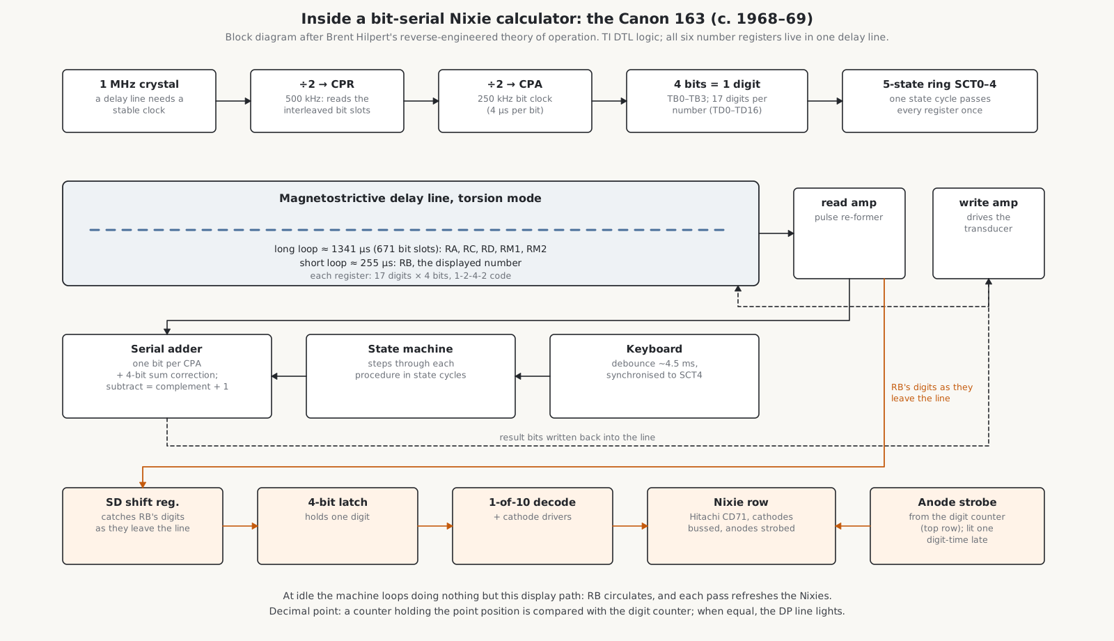
- Logic: Texas Instruments DTL integrated circuits, mostly NAND gates whose outputs can be wired together, with house numbers SN39xx and SN45xx that match standard DTL types. Most flip-flops are pairs of NAND gates with capacitor triggering, cheaper at the time than full master-slave flip-flops.
- Clock: a 1 MHz crystal. Most calculators of the era made do with an RC oscillator; the delay line needs a stable frequency, so the 163 has a crystal. It is divided to 500 kHz (signal CPR, which times the reading of interleaved bit slots in the line) and to 250 kHz (CPA, the bit clock: 4 µs per bit). Four bits make a digit, seventeen digits a number, and a five-state ring counter steps through the registers.
- Memory: six registers of 17 digits, each 68 bits, all held in one torsion-mode delay line. A long loop of 1341 µs holds five of them (the previous operand, two temporaries and two memories); a short loop of about 255 µs holds the displayed number, so that the display can be refreshed quickly. Decimal-point positions and signs are kept in flip-flops, not in the line.
- Arithmetic: a serial adder working one bit per clock with a four-bit sum-correction register. The digits are coded not in plain binary (8-4-2-1) but in a 1-2-4-2 code, chosen because in it subtraction is just a matter of complementing the bits of the number being subtracted and adding 1 at the carry input.
- Control: a state machine that steps through each procedure, addition, multiplication, division or square root, in a sequence of state cycles. At idle it loops in one state, doing nothing but refresh the display.
- Keyboard: each key press triggers a debounce monostable of about 4.5 ms, synchronised to the register cycle before it is acted on.
5.4.2 The Sony SOBAX 2500
The Sony 2500 of 1969–70 uses a longitudinal-mode delay line about 362 cm long, time-multiplexed into sixteen channels: fifteen registers of 64 bits (sixteen digits) and a synchronising channel, 1,024 bits in all. Its logic is Sony’s own 500-series integrated circuits, running from +4 V. It also uses the 1-2-4-2 code. Its most unusual feature is the clock. Instead of a crystal, its master oscillator is an RC oscillator acting as the voltage-controlled oscillator of a phase-locked loop, locked to synchronising marks recorded in the delay line itself, so that the clock stays in step with the line itself. Hilpert’s theory of operation explains it in 52 pages.
5.5 Capacitors: the Toshiba BC-1411
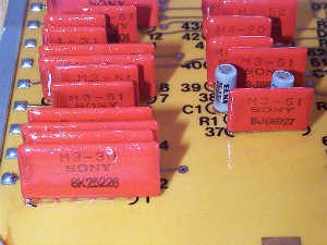
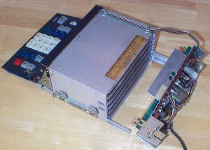
The Toshiba BC-1411 of 1966 is a bit-serial machine of 286 transistors running at 40 kHz, but it uses neither a delay line nor cores. Its registers are 180 discrete capacitors, fifteen registers of twelve bits, each capacitor holding one bit as a charge. A charge leaks away, so each bit must be read and rewritten continually, exactly as in the dynamic RAM chips of the 1970s and since; the BC-1411 does it with discrete parts on a circuit board.
5.6 MOS chips: the end of the line
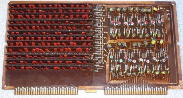
From 1967 the Japanese makers began to use MOS integrated circuits, at first in small numbers of gates per chip: the Sharp Compet 22 used 83 first-generation Hitachi MOS chips, the Friden EC-1113 108 of them. MOS transistors are slow but tiny and use very little power, and a MOS chip can hold a long dynamic shift register, which does the job of a delay line in silicon.
The Friden EC-1115 of 1970 shows the result. Its 45 Hitachi HD3100-series PMOS chips are of eight types, from simple gates and flip-flops to the HD3109, a 68-bit dynamic shift register, 17 digits of four bits, which holds a whole number on one chip. Three registers, R1 to R3, circulate through the chips, a delayed full adder (the HD3112) does the arithmetic, and the logic runs between 0 and −24 V. Its display, described in the previous volume, uses discrete transistors. The Hitachi chip data sheets are in the Library.
By 1969–71 a calculator needed only a handful of large chips. The SCM Cogito 412 uses eight AMI MOS-LSI chips; the Casio 121-K four Fairchild chips; the Monroe 610 a four-chip Texas Instruments set; the Friden EC-1117 nine Hitachi chips. What remains on the board is mostly the Nixies, their high-voltage drivers and the power supply, which is why the vacuum-fluorescent display, which MOS chips could drive directly, swept the Nixie away within two years.
Comments (0)