CRT Calculators · Volume 4
Theory of Operation: The CRT and Its Drive Circuits
Every CRT calculator faced the same problem: to turn a stream of digits, coming out of memory one at a time, into rows of readable figures on a glass screen, refreshed fast enough not to flicker, with circuits cheap and reliable enough for an office machine. This volume explains the tube itself, then follows the Friden EC-130’s display circuits through the factory service manual, and ends with the different solutions of Hewlett-Packard, Wyle and Descal.
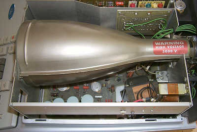
4.1 The tube
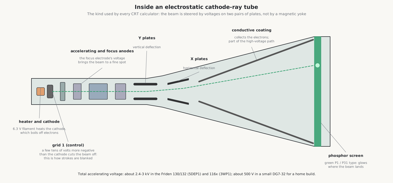
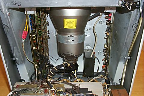
A cathode-ray tube is an evacuated glass bulb with an electron gun in its narrow neck and a phosphor screen on the inside of its wide face. All the calculator tubes are of the kind used in oscilloscopes, with electrostatic deflection: the beam is steered by voltages on two pairs of metal plates inside the neck, not by the magnetic coils of a television tube. Electrostatic deflection needs little power and responds in a fraction of a microsecond, which is what a machine drawing digits line by line needs.
From the back of the tube forward:
- Heater and cathode. A 6.3 V filament heats the cathode, which gives off electrons.
- Control grid (grid 1). A cylinder round the cathode. Made a few tens of volts more negative than the cathode, it repels the electrons and cuts the beam off; made less negative, it lets them through. This is how a calculator draws only the strokes it wants: the beam is always moving, and the grid turns it on and off.
- Accelerating and focusing anodes. Cylinders at high voltage relative to the cathode pull the electrons forward into a beam and act as an electron lens. The focus control sets one of these voltages so that the beam converges to a fine spot on the screen; the astigmatism control corrects a spot that is sharp in one direction but not the other.
- Deflection plates. First the vertical (Y) pair, then the horizontal (X) pair. A voltage difference between the plates of a pair bends the beam towards the more positive plate.
- Screen. The phosphor glows where the beam lands. The conductive coating inside the bulb collects the electrons and returns them to the supply.
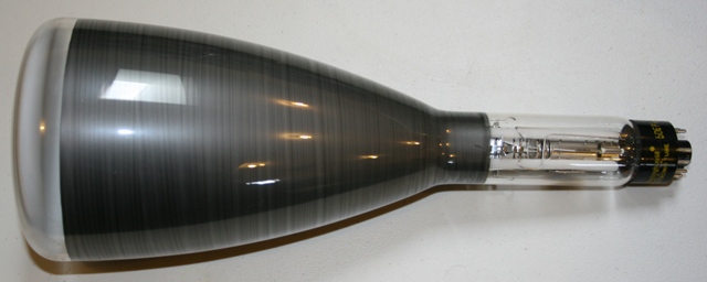
The tube type numbers follow the American system: in 5DEP1, the 5 is the screen diameter in inches, DE a serial code, and P1 the phosphor, a green one of medium persistence. The Friden 116x machines use the 3WP1, a 3-inch tube with the same P1 phosphor; the Victor 14-321 an RCA type 4499; the HP 9100 a tube of its own, HP part 5083-1551. Phosphors differ in colour and in how long they glow after the beam has passed; a medium-persistence phosphor is bright, and its glow fades in a few milliseconds, which hides the redrawing. The Library holds a guide to CRT phosphors for experimenters.
4.2 Strokes, not a raster
A television scans its whole screen line by line and makes pictures by changing the brightness as it goes: a raster. The CRT calculators do something different. Their beam is steered along the actual lines of each digit, a stroke or vector display, so it only travels where there might be something to draw. Almost all the makers used the same trick to keep the electronics simple: the beam traces the same figure-8 path for every digit, and the digit’s value only decides which parts of the path are lit. The collectors’ phrase for the resulting characters is “pieces of eight”.
Drawing a row of digits therefore needs four things:
- a position for each digit, stepping from place to place along the row and from row to row;
- a stroke waveform that moves the beam along one segment of the figure 8;
- a start point for each stroke, relative to the digit’s position;
- a blanking signal that lights only the strokes the digit needs.
4.3 The Friden display, stroke by stroke
4.3.1 The patent’s version
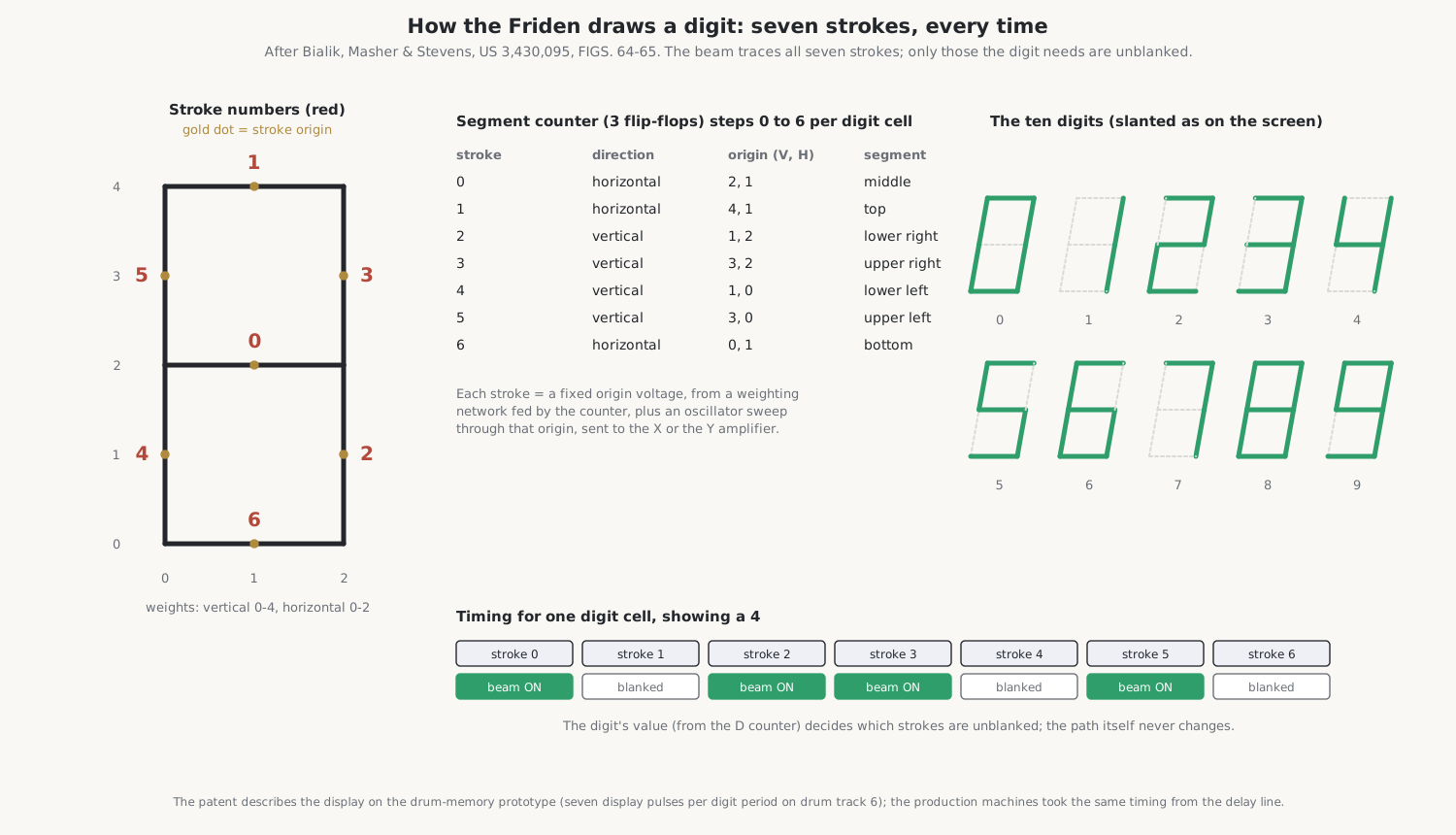
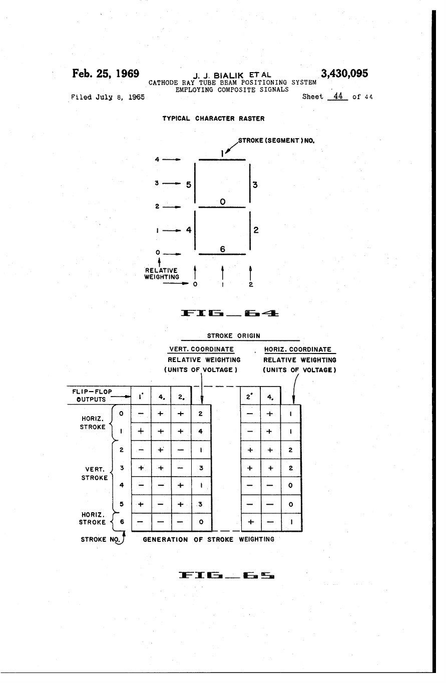
The display was designed for Friden by the Stanford Research Institute and patented by Jack Bialik, Dale Masher and William Stevens as US 3,430,095, “Cathode ray tube beam positioning system employing composite signals”. As described in the patent, the display was built for the prototype’s magnetic drum: a three-flip-flop segment counter steps through seven strokes for every digit cell, one per display pulse from the drum. For each stroke a network of weighted resistors sets the stroke origin, the centre of that segment, and an oscillator sweeps the beam through the origin, horizontally or vertically. Strokes 0, 1 and 6 are horizontal (middle, top, bottom); 2, 3, 4 and 5 are vertical (lower right, upper right, lower left, upper left). Staircase generators add the position of the digit on the screen.
4.3.2 The production machine
The production EC-130, as described in its service manual, works on the same principle with more strokes and a little refinement. The deflection voltage on each axis is the sum of four signals:
- The segment generator makes a linear sawtooth: a capacitor charging towards −80 V through a 50 kΩ adjustable resistor and a 22 kΩ resistor, discharged at the end of each segment. Twelve segments are produced in each 288 µs column time, one every 24 µs, whether or not anything is being displayed. The adjustable resistor sets the length of the segments, which is the size of the digits.
- The segment switching circuits send the sawtooth to the horizontal or the vertical channel, according to whether the current segment is a horizontal or a vertical stroke.
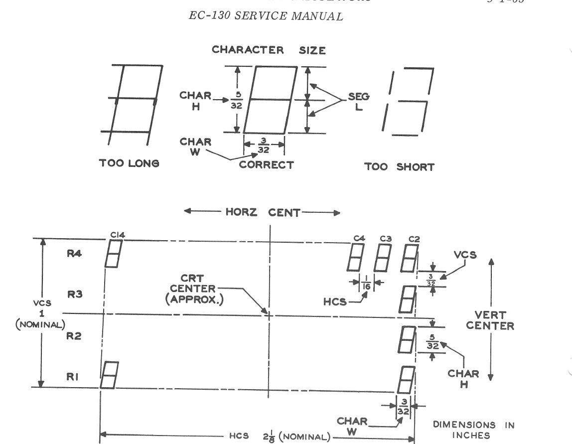
- The dot generators are resistor dividers from a zener-regulated −8 V that set where each segment begins. A vertical segment may start at vertical level A or B and horizontal level D or E, four possible starting points; a horizontal segment at vertical level A, B or C and horizontal D, E or F, six points.
- The staircase generators position the digit. The horizontal staircase is a capacitor charged in fourteen equal steps of about 0.1 V, one per column (C1 to C14), then discharged, so the digits march across the screen from right to left. The vertical staircase gives four levels, one for each register R1 to R4, selected by the two display-timing flip-flops M and N.
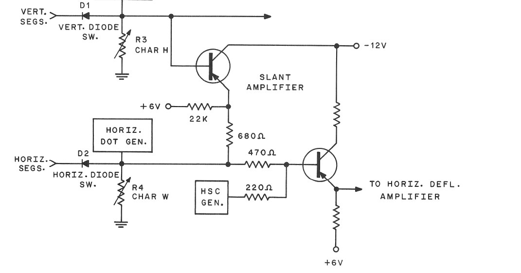
A slant amplifier adds a little of the vertical signal to the horizontal one, so that the top of each vertical stroke is displaced sideways and the digits lean, which the manual calls “a more pleasing display”. The decimal point (segment 13) and the minus sign (segment 14) are drawn with their own offsets.
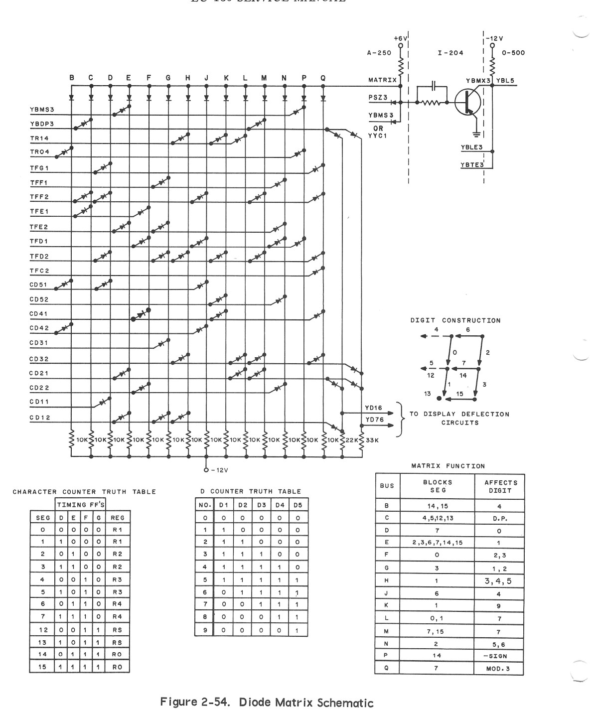
The diode matrix decides what is lit. It decodes the digit in the D counter and the segment timing into the unblanking signal: a grid of diodes in which each row is a timing or digit signal and each column a group of segments (“blocks segments 14, 15 … affects digit 4”). Its corner drawing, “digit construction”, shows how the segments make up the figure 8.
Blanking. In normal operation the tube is held cut off. A blanking pulse from the unblanking logic lifts the grid out of cut-off for the duration of each wanted segment. Because the pulse is capacitor-coupled to the grid, a diode across a 2.2 MΩ resistor restores the DC level; an INTENSITY potentiometer sets the grid’s resting bias, and its arm is held at AC ground by a 0.1 µF capacitor.
Refresh. One register is drawn in each pass of the delay line: R1 for all its columns, then R2, R3 and R4, as the M and N flip-flops step. Each row is therefore redrawn once in every four passes, about fifty times a second (my calculation from the 4.95 ms line); the medium-persistence phosphor bridges the gaps. The four-counter machines draw the bottom register twice in each cycle, which is why it looks brighter. The deflection circuits run all the time, but the display is blanked whenever the machine is calculating.
4.4 The deflection amplifiers
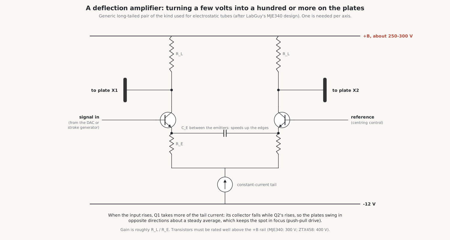
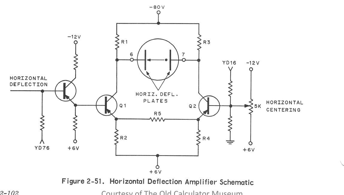
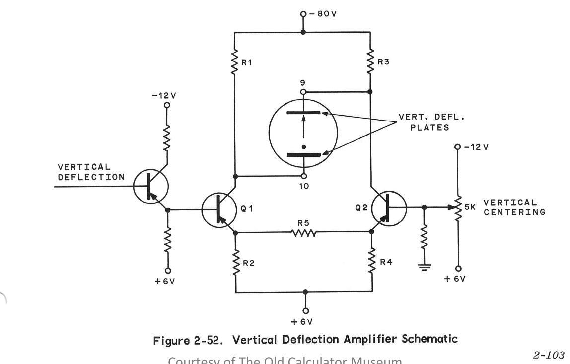
The dot, segment and staircase voltages are a few volts at most; the plates need tens of volts. Two identical amplifiers, one per axis, provide the gain. The service manual describes them as class A, push-pull, emitter-coupled differential amplifiers with a gain of about 35. An emitter-follower drives the base of the first transistor of a pair; the second transistor’s base sits at a reference set by a 5 kΩ centring potentiometer; the collectors are fed from the −80 V supply through load resistors and each drives one plate of the pair. As the input changes, the current shifts from one transistor to the other, one plate swinging up while the other swings down. Push-pull drive keeps the average plate voltage constant, which keeps the spot in focus across the screen.
4.5 The high-voltage supply
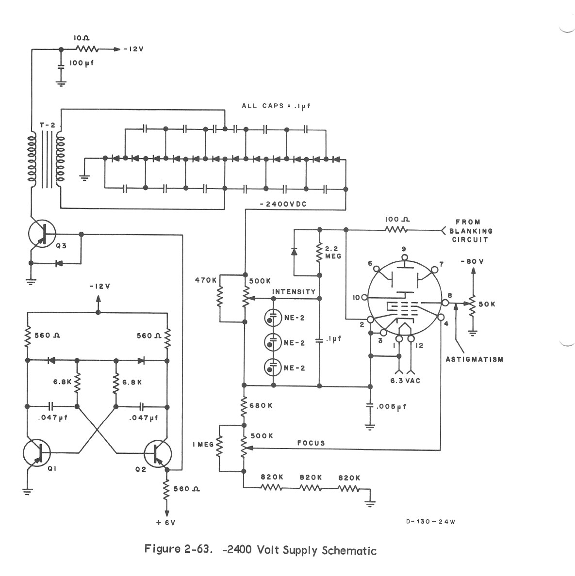
The tube needs about 2,400 V between its cathode and its final anode. The EC-130 makes it in an unusual way, described in its service manual as an “oscillator” power supply:
- A 2 kHz multivibrator. Two transistors (Q1, Q2) switch alternately at a rate set by their timing capacitors and resistors, about 2,000 times a second.
- A transformer driver. Q2’s output switches a power transistor, Q3, which connects the transformer’s primary across the −12 V supply. When Q3 switches off, the collapsing field gives an “inductive kick” that adds a further 12 V, so about 24 V appears across the primary. A 10 Ω and 100 µF filter keeps the 2 kHz switching out of the −12 V supply.
- Step-up. The secondary gives about 400 V. Driving the transformer at 2 kHz instead of the 60 Hz mains lets the same number of turns produce a higher voltage, because the rate of change of current is so much greater.
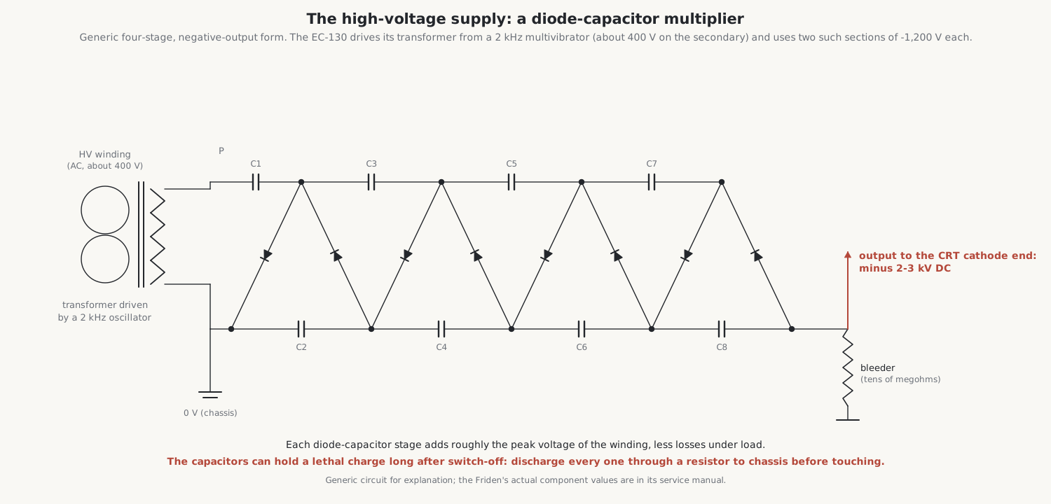
- A voltage multiplier. A ladder of diodes and 0.1 µF capacitors multiplies the 400 V peak to the full voltage. The transformer is connected between two multiplier sections, so each need only make −1,200 V, which eases the insulation.
- The tube’s electrodes. The −2,400 V goes to the cathode end through the INTENSITY and FOCUS potentiometers in a resistor chain. Three NE-2 neon lamps in series between grid and cathode keep the voltage between them below about 210 V, because a larger difference could cause arcing inside the tube. The focus and astigmatism controls set the anode voltages.
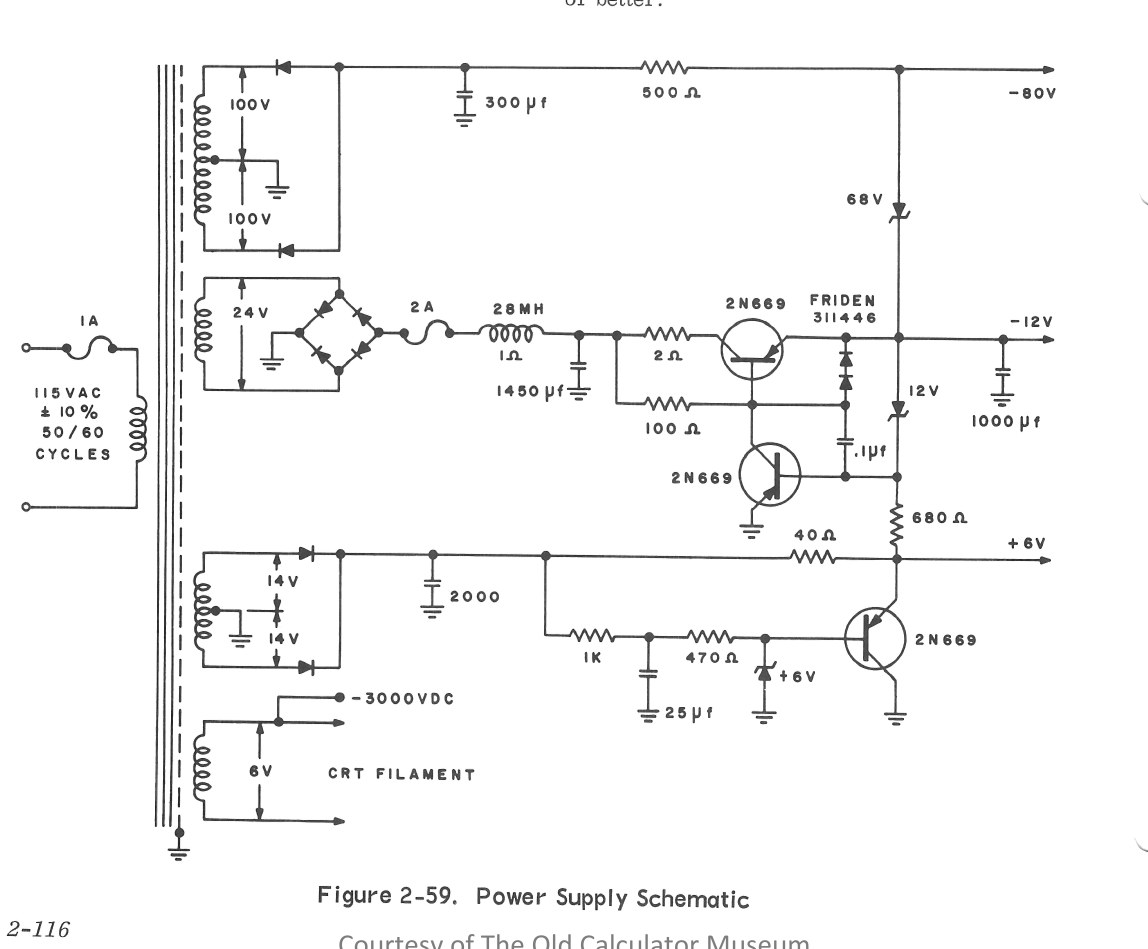
The other supplies come from the mains transformer: about −80 V (a 200 V full-wave winding, a 300 µF reservoir capacitor and a 500 Ω series resistor, with a zener diode to the −12 V supply), −12 V and +6 V (each with a 2N669 series-pass regulator), and the 6.3 V heater winding.
The high voltage is dangerous. The multiplier capacitors can hold a charge after the machine is switched off. The repair volume sets out how to work on these machines safely.
4.6 Other ways to draw a digit
4.6.1 Hewlett-Packard: an E and an I
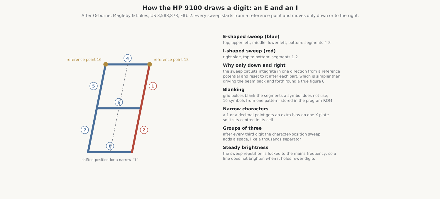
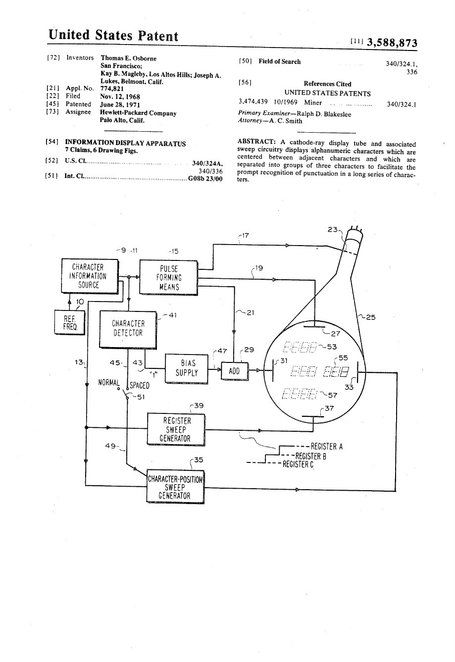
The HP 9100’s display, patented by Tom Osborne, Kay Magleby and Joseph Lukes as US 3,588,873, forms its figure 8 from two simpler patterns side by side: an E-shaped sweep (top, upper left, middle, lower left, bottom) and an I-shaped sweep (the right side, top to bottom). Each starts from a fixed reference point and moves the beam only down or to the right, so the sweep circuits integrate in one direction only and are reset to their reference after each part. Grid pulses blank the parts a symbol does not use, giving sixteen symbols from the one pattern, and the patterns themselves are stored in the program ROM. A narrow character such as a 1 or a decimal point gets an extra bias on one horizontal plate so that it sits centred in its space. After every third digit the character-position sweep inserts a gap, so long numbers are grouped in threes. And the repetition of the sweep is locked to the mains frequency, so that a line holding few digits is not redrawn more often, and brighter, than a full one.
4.6.2 Wyle: sine and cosine
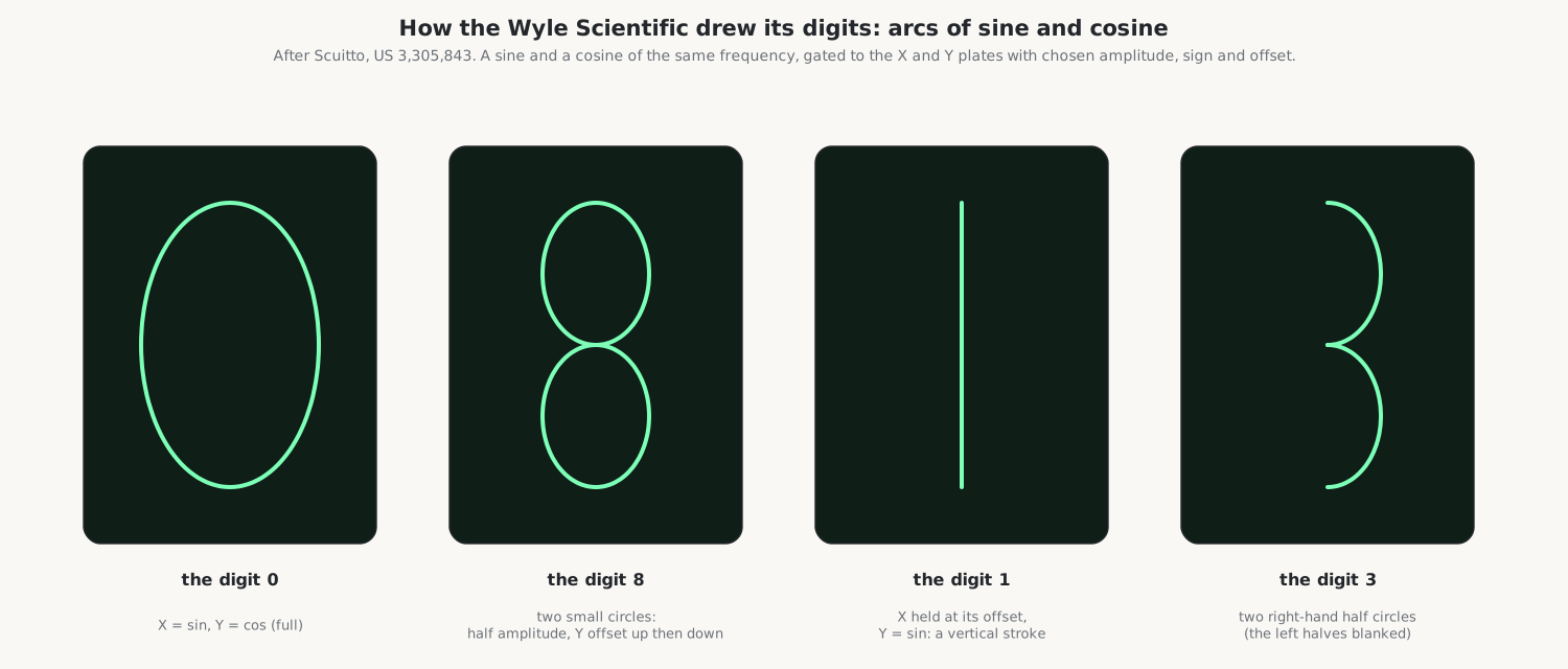
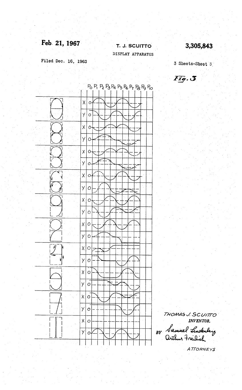
The Wyle Scientific drew its digits not from straight strokes but from arcs. In Thomas Scuitto’s patent, US 3,305,843, a square wave from the bit counter is divided by four and filtered into a sine and a cosine of the same frequency. For each part of a digit, gates choose which wave goes to the X plates and which to the Y plates, at full or half amplitude, normal or inverted, with a chosen DC offset. A sine on X and a cosine on Y make a circle, or an ellipse if the amplitudes differ; two small circles one above the other make an 8; a sine on Y alone makes a vertical line. Intensity feedback compensates for the beam moving faster on some parts of a curve than others. The result looks handwritten. The method goes back to K. E. Perry and E. J. Aho of MIT’s Lincoln Laboratory, who described generating characters from sine and cosine harmonics in Electronics in 1958.
4.6.3 Descal: slopes and steps
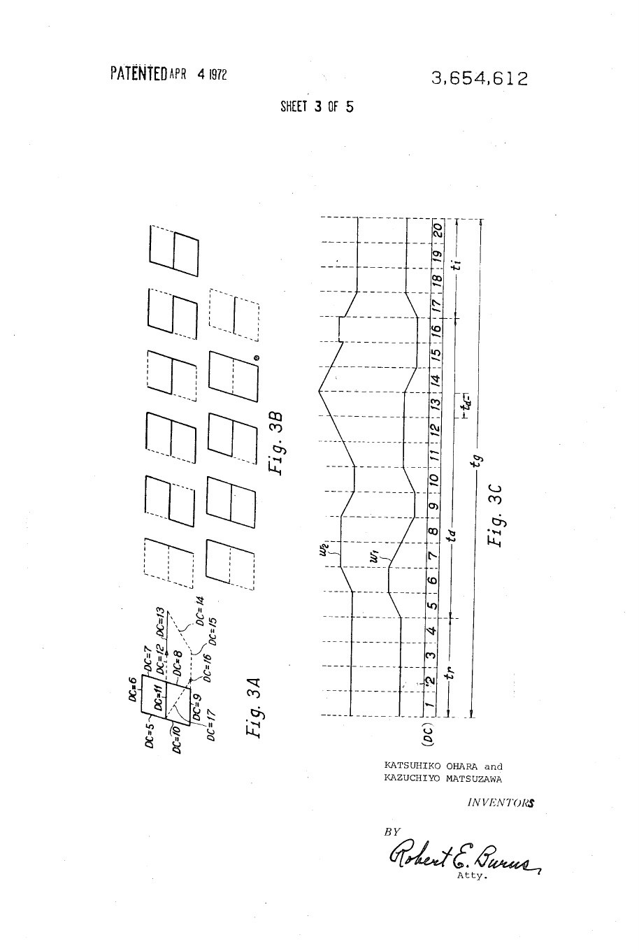
The Japanese Descal ASI-500 (US 3,654,612) draws its digits with slope and step sweeps and a diode read-only memory that blanks the unused parts of each digit; the same counters serve both the arithmetic and the display. Its long-persistence blue-white phosphor makes changing digits seem to melt from one to the next.
4.6.4 Cogito, Victor and the rest
The SCM Cogito 240 sets its stroke sequences with a diode-resistor “ROM” and draws seven-segment figures with half-height zeros on a blue-green tube. The Victor 3900 draws figure-8 digits from straight strokes made by a stroke-generator board of discrete parts. One account says the 3900’s characters were formed inside the tube like a Charactron, but the museum’s photographs and Victor’s own patent contradict it. The Victor 14-321 and the Busicom machines also use vector-drawn seven-segment digits.
4.7 Why the tubes burn
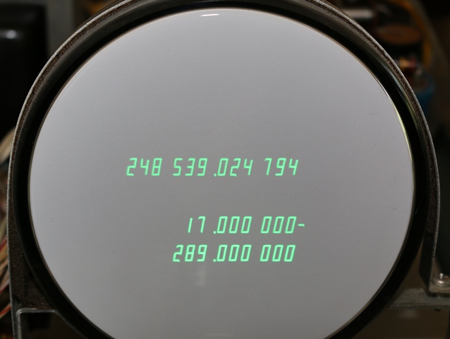
A phosphor wears where the beam strikes it. A display that shows the same digits in the same places for years, rows of leading zeros especially, leaves a permanent shadow of them in the glass. The Friden 1162 does not suppress leading zeros and often shows this burn-in; the 1166, which does suppress them, is less affected. A spot left stationary at full brightness can burn a hole in the phosphor in minutes, which is why every one of these displays keeps its beam moving and blanked when there is nothing to draw.
Comments (0)