CRT Calculators · Volume 8
Building a Reproduction
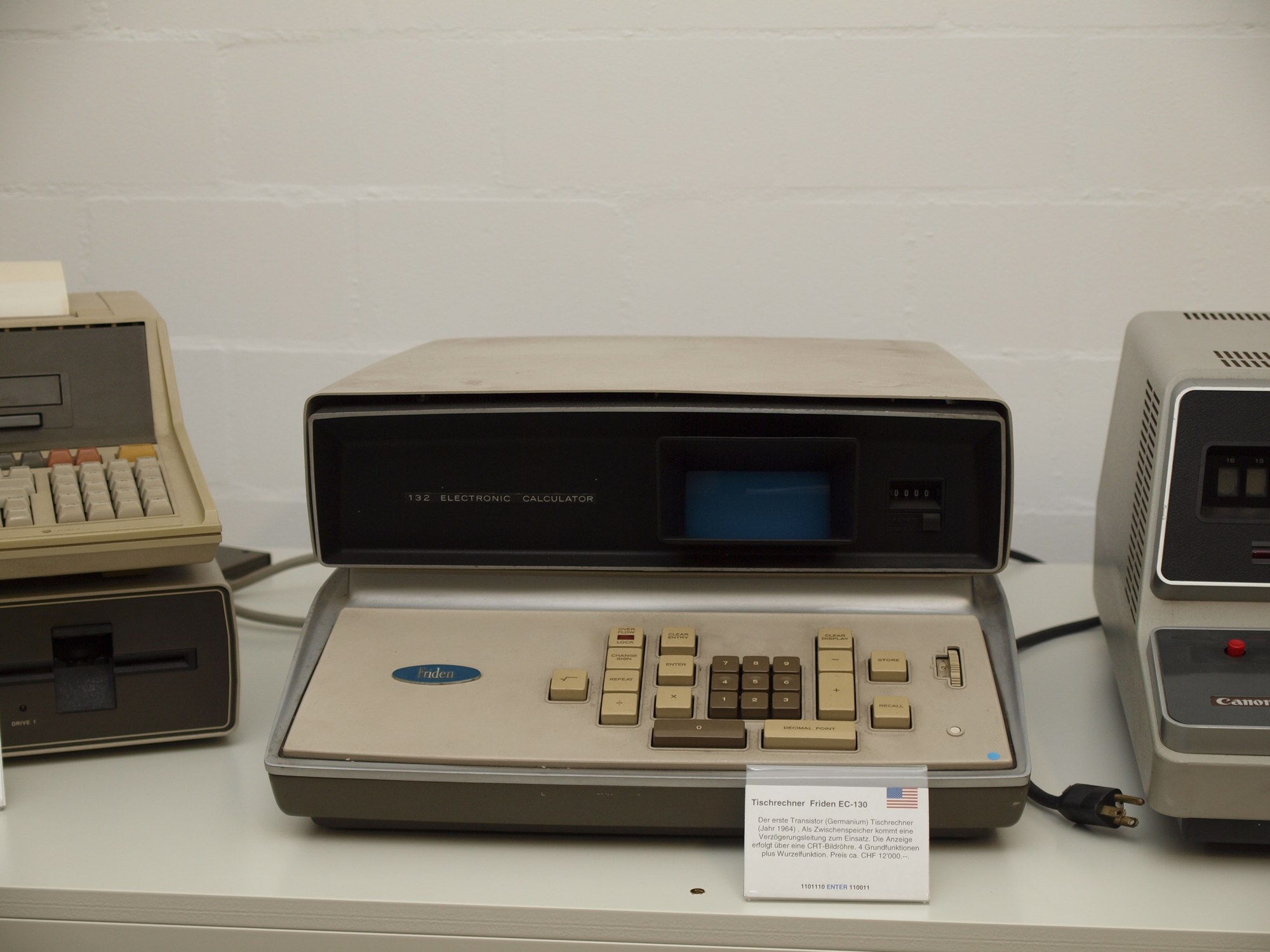
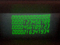
An original CRT calculator is rare, heavy and fragile, and its tube and delay line cannot be replaced. A reproduction can be built today that looks and behaves like one: a small electrostatic tube drawing slanted figure-8 digits in green, four rows of them, driven by a modern microcontroller running the calculator. No one appears to have built one yet: searches of Hackaday, Hackaday.io, Instructables and GitHub found scope clocks and vector games but no CRT calculator. This volume sets out a design that can be built from parts available now, the choices along the way, and the safety rules that matter.
It is a design, not a finished build. The circuits are proven in other projects, cited below, but this combination has not been tested, and the prices are estimates.
8.1 What to copy
The Friden EC-130 is the natural model: its operation is simple, its four-row display is the classic look, and its documentation is complete. The original’s figures:
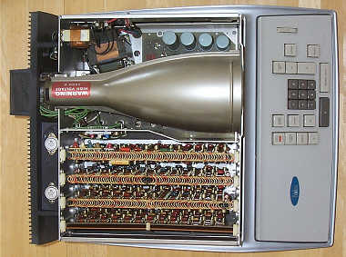
- a 5-inch round tube showing four rows of 13 digits plus sign, slanted figure-8 digits in green P1 phosphor;
- a keyboard of ten digits, the decimal point, and the operation keys ENTER, REPEAT, CHANGE SIGN, + − × ÷, STORE, RECALL, CLEAR ENTRY, CLEAR ALL and OVER-FLOW LOCK, with a decimal-point thumbwheel;
- a cabinet 18 inches wide, 21½ deep and 18 high, weighing 42 pounds.
A full-size replica is large. A cabinet at about 60–70% scale round a 7 cm tube keeps the proportions and fits on a desk. The HP 9100’s flat rectangular screen could be imitated instead with a rectangular tube such as the Soviet 6LO1I.
8.2 Three ways to get digits on a CRT
- Use an analogue oscilloscope as the display. A used Tektronix 2215 costs about $150–175. The calculator board drives its X and Y inputs in X-Y mode and its Z input for blanking. There is no high-voltage work at all, but it looks like an oscilloscope, unless the scope’s tube and supply are moved into a replica cabinet.
- A small tube with its own supply: the true reproduction, and the design below.
- A look-alike. A round LCD (a 1.28-inch GC9A01 costs about €8–11) rendering green digits with a simulated glow and fade. It is safe and cheap but too small for a Friden bezel, and it is not a CRT.
8.3 The tube
Electrostatic tubes from oscilloscopes are still sold as new old stock. The best candidates:
Table 1 — Electrostatic tubes from oscilloscopes are still sold as new old stock. The best candidates
| Tube | Screen | Supply | Deflection | Notes |
|---|---|---|---|---|
| DG7-32 (3AMP1A, CV2431) | 7 cm round | about 500 V | very sensitive: 0.35–0.43 mm/V (plates D1), 0.24–0.30 mm/V (D2) at 500 V | green, medium persistence; one of the most widely made scope tubes; new old stock about €67 plus postage (eBay.de, June 2025) |
| 3RP1 / 3RP1A | 3 inch | 1,500–2,000 V | sensitive (figure not found) | the tube Cathode Corner recommends for its scope clocks; the A has a flat face |
| 6LO1I (Soviet) | 5.5 cm rectangular | not confirmed | not confirmed | about $30–35 new from Ukraine; rectangular like the HP 9100’s |
| 5DEP1 | 5 inch round | up to 2,750 V | the Friden’s own tube; availability unknown, but tested by LabGuy with the amplifier design below |
The DG7-32 is the practical choice. At 500 V it needs only about 170 V between a pair of plates for a 6 cm sweep (60 mm ÷ 0.35 mm/V, my arithmetic), or about ±85 V on each plate, which simple transistor amplifiers on a 250 V supply can provide. The rule of thumb is that a tube run at a lower anode voltage deflects more easily but is dimmer, and a calculator display needs only modest brightness indoors.
8.4 The design
8.4.1 Power: low voltage in, high voltage made inside
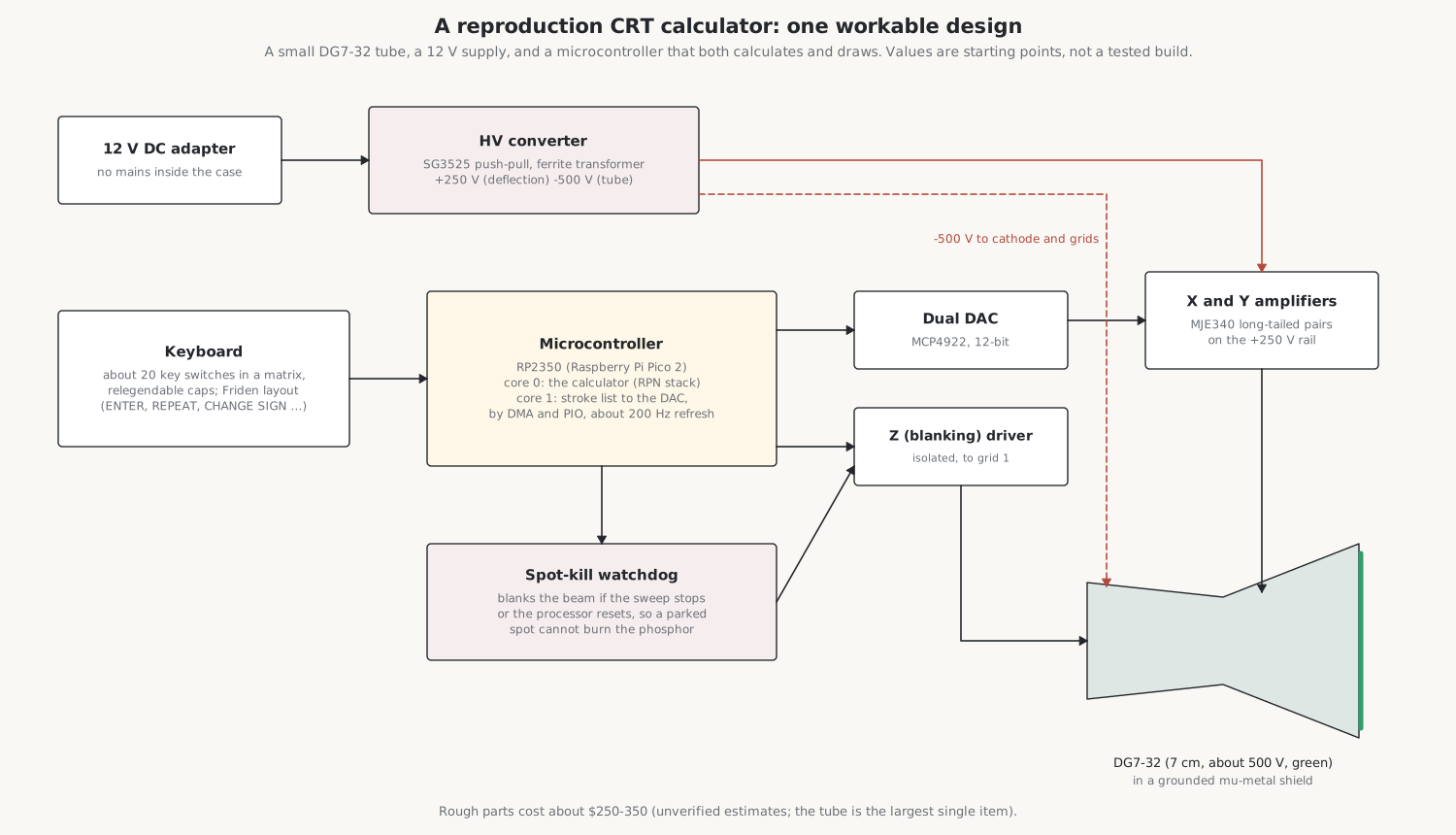
The safest arrangement keeps the mains outside the case. A 12 V DC adapter feeds a small push-pull converter built round an SG3525 controller, two MOSFETs and a ferrite transformer, the approach of Mark Atherton’s VDM3 vector-drawing machine, which made about +210 V at 7 mA for its deflection amplifiers and −600 V at 1 mA for its tube. This design needs about +250 V for the deflection amplifiers and −500 V for the tube’s cathode and grids. A switching converter running at tens of kilohertz also keeps the stray magnetic field of a mains transformer away from the tube, whose beam it would bend.
Every high-voltage output needs a bleeder resistor to discharge it when the power is off.
8.4.2 The deflection amplifiers
Each axis has a long-tailed pair of high-voltage transistors: two MJE340s (rated 300 V) or ZTX458s (400 V), their emitters joined through degeneration resistors to a constant-current tail, their collectors fed from the 250 V supply through load resistors, and each collector driving one plate. This is the circuit of the Friden’s own deflection amplifiers, and of LabGuy’s electrostatic-CRT project, which used MJE340s with a gain of about 100 (1.5 kΩ emitter, 150 kΩ collector resistors) to turn 0–3 V into 0–300 V on each side, and tested it with a 3RP1A, a 2BP1, a 5UP1 and a 5DEP1. His lessons: a small capacitor across the emitters (3.9 nF in his case) fixes the frequency response; an expensive fast op-amp in the loop just oscillated; the 300 V board runs hot; and switching noise from the supply smears the trace. The principle is drawn in the CRT volume.
8.4.3 Blanking and the spot-kill
The beam is turned off and on through the tube’s grid 1, which sits near the −500 V of the cathode, so the blanking signal from the microcontroller must cross that voltage: through a high-voltage optocoupler or a small isolated driver, or capacitor-coupled with a DC restorer as Friden did. Add a spot-kill circuit that holds the beam off whenever the sweep stops or the processor resets. A beam left still at full brightness burns the phosphor in moments; the datasheet of the Soviet 8LO29I tube makes automatic blanking on sweep failure a requirement, and Trammell Hudson’s vector-display notes record a burn made while reflashing the firmware.
8.4.4 The logic: one chip that calculates and draws
An RP2350 (the Raspberry Pi Pico 2) suits the job: it has two cores and programmable I/O.
- Core 0 runs the calculator: a behavioural copy of the Friden 130, with the four-register stack, 13 digits, a fixed decimal point chosen by a thumbwheel or switch, a store register, and the same key actions as the original, described in the operating volume.
- Core 1 draws the display. For each of the four rows and each digit place, it sends the beam through the digit’s strokes, lighting only the segments the digit needs, exactly as the Friden did. The list of X, Y and blank values streams to the DAC by DMA and PIO, as in Oli Wright’s Velociraster, which drove two parallel DACs from a Pico this way.
- The DAC: an MCP4922 dual 12-bit converter, about $3, with a settling time of 4.5 µs per point. A full frame of 4 rows × 14 places × 7 strokes is 392 strokes; at eight points a stroke that is about 14 ms, a refresh of about 70 Hz (my arithmetic), enough to avoid flicker. A faster parallel DAC or a resistor ladder driven by PIO would give smoother lines. A little low-pass filtering, or the amplifiers’ own limited bandwidth, turns the DAC’s steps into smooth strokes, the effect the CDC 6600’s console relied on.
Three lessons from vector-display builders: keep every drawing path the same length in time, or the beam dwells and makes bright dots at line ends; never let the beam park; and a cheap internal DAC, such as the ESP32’s 8-bit one, gives jagged lines and noise.
8.4.5 The keyboard
About twenty key switches in a matrix. Cherry MX-type switches with relegendable two-part caps (Adafruit’s cost $4.95 for ten) are the simplest. Keys shaped like the Friden’s would have to be 3D-printed or cast in resin. The Friden’s habit of locking a function key down until the operation finished can be imitated in firmware.
8.4.6 The cabinet
3D-printed or laser-cut panels over an aluminium chassis, with a grounded steel or mu-metal shield round the tube. The shield keeps stray magnetic fields from bending the beam and helps contain the glass if the tube is ever broken. Clamp the tube firmly at its face and neck.
8.5 A rough parts list
Table 2 — A rough parts list
| Part | Choice | Rough cost |
|---|---|---|
| Tube | DG7-32, new old stock | €67 plus postage |
| Tube socket | to suit the tube’s base | $5–15 (not verified) |
| Shield | mu-metal | $20–60 (not verified) |
| Microcontroller | Raspberry Pi Pico 2 (RP2350) | about $5 |
| DACs | two MCP4922 (X/Y, and Z or intensity) | about $3 each |
| Deflection amplifiers | four MJE340 and resistors | about $10 |
| HV converter | SG3525, two MOSFETs, ferrite core, HV diodes and capacitors, bleeders | $25–40 (not verified) |
| Blanking and spot-kill | HV transistor or optocoupler, comparator | about $5 |
| Keyboard | about 20 switches and caps | $15–25 |
| Power | 12 V, 2 A adapter | about $10 |
| Cabinet | printed or cut panels, aluminium | $40–100 (estimate) |
| Total | about $250–350 |
A shortcut is to buy a scope-clock kit for the high-voltage and deflection side. Howchon’s OSC4.6 kit ($120 without tube) already drives a DG7-32 or 6LO1I from a 600 V multiplier, but whether its deflection inputs can be driven from an outside board has not been checked, and its multiplier runs from the mains.
8.6 Doing it the hard way: the real Friden logic
A behavioural copy is the practical route, but the Friden’s logic is documented down to every gate in its logic schematics and service manual, with the timing in Ragen’s patents. A gate-level copy in an FPGA is feasible, with a block-RAM shift register standing in for the delay line and the A, B, C and D counters rebuilt as switch-tail counters. Brian Cauchi built a Friden EC-130 in VHDL on a Xilinx Spartan-3 board in 2007, in about four weeks, as a copy of the machine’s behaviour rather than its circuits. The HP 9100 cannot yet be copied this exactly: its ROM has never been published, and a 2025 effort on the HP Museum forum to read it out had not reported success. The existing 9100 emulators, by Andreas Mueller and Tony Duell, are behavioural.
8.7 Prior art worth studying
- Cathode Corner’s scope clocks (David Forbes): a Teensy drives a 3-inch tube as an X-Y display; the schematics and firmware are published.
- LabGuy’s World: the MJE340 electrostatic deflection amplifier, tested on the Friden’s 5DEP1.
- The Ultra-Simple Oscilloscope (electronixandmore): a transformer supply of about +350 V and −650 V, ZTX458 push-pull deflection, tested with 2AP1, 3BP1, 3JP1 and 3RP1 tubes (the 3RP1 “bright, sensitive”).
- VDM3 (Mark Atherton): the SG3525 low-voltage-input converter and a D7-16G tube.
- Velociraster (Oli Wright): Pico, DMA and PIO driving vector DACs.
- Perry and Aho, “Generating Characters” (1958), and the Wyle and Friden display patents in the Library, for the original character-drawing methods.
8.8 Safety
The tube’s supply in this design is only −500 V, but that is lethal, and the 250 V deflection supply can deliver more current than the tube supply. The rules are the same as for the originals in the repair volume:
- keep the mains outside the case (the 12 V adapter);
- bleeder resistors on every high-voltage output, and discharge before touching;
- no exposed high voltage with the cover on; an interlock on the rear panel is good practice;
- a firmly clamped tube inside a grounded shield;
- the spot-kill, to protect the tube.
Comments (0)