Calculator Watches · Volume 4
Inside a Calculator Watch
Open the back of a modern Casio calculator watch and there is not much to see: a plastic frame holding a circuit board the size of a postage stamp, a coin cell, a display, and a black blob of epoxy where the chip should be. Everything the watch does, the clock, the calendar, the five alarms, the calculator and the Data Bank, is done by that one chip.
Casio publishes no circuit diagram for module 2888, and nobody has published a teardown of one. This volume describes the parts that Casio’s guide and my own watch show for certain, and fills in the rest from documented watch chips and from a teardown of an older Casio Data Bank. Where it does that, the text says so.
4.1 The module as a whole
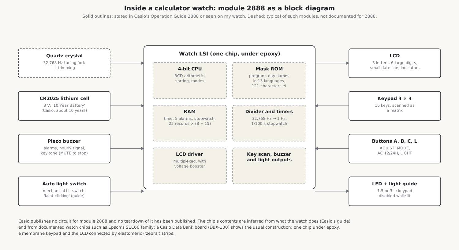
An owner who opened a Casio DBX-100, a Data Bank of 1988, for repair found the arrangement that has served Casio ever since: the “main chip is a proprietary digital watch IC, buried under a blob of epoxy”, mounted directly on the board (chip-on-board), so that it carries no markings at all. Around it were many test points for factory testing, a keypad made of two layers of plastic film, elastomeric strips connecting the board to the display and to the keypad’s contact tail, and a small spring touching a piezoelectric buzzer. Who makes Casio’s watch chips is not public. The best clue is a die photograph of the chip in Casio’s F-91W, published by the chip-imaging laboratory Zeptobars, whose image files are labelled OKI, the Japanese semiconductor maker now part of ROHM.
4.2 The display
The display is a twisted-nematic liquid-crystal display, the kind used in digital watches since the mid-1970s. A thin layer of liquid crystal lies between two glass plates coated on the inside with transparent electrodes and with alignment layers that twist the molecules through 90° from one plate to the other. Crossed polarizing films outside the glass let light through the twist, so the display is pale; a voltage across a segment untwists the molecules there, and the segment goes dark. The effect was patented in 1970–71 by Wolfgang Helfrich and Martin Schadt at Hoffmann-La Roche in Switzerland and, independently, by James Fergason in the United States. The liquid crystal draws almost no current, only enough to charge the tiny capacitor that each segment forms, which is why an LCD watch can show the time continuously for years on one cell where the LED watches of the 1970s lit their digits only on demand.
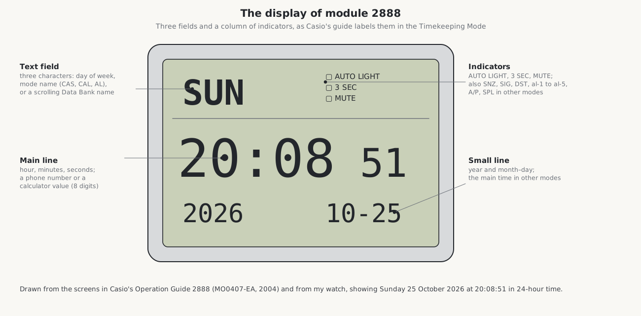
Module 2888’s display has three parts. A text field at the top shows three characters, the day of the week, a mode name or a scrolling Data Bank name; since it has to draw 121 different characters, from the Latin alphabet with its accents to Cyrillic, it is very probably a small dot matrix rather than fixed segments, though no close photograph confirms it. A main line of six large seven-segment digits shows the time, a calculator value or a telephone number, and a small line below shows the date or the time in other modes. Indicators around them show the state of the alarms, the light, the key tone and daylight saving time.
4.2.1 Multiplexing
A display with several hundred segments cannot have a wire to each one. Watch displays are multiplexed: the segments are wired in a grid against a few shared back electrodes, the commons, and the chip energizes the commons one after another, many times a second, setting each segment line to darken the segments wanted on that common. Liquid crystal cannot tolerate a steady voltage: a DC component “as small as 50 mV”, in Wikipedia’s account of the technology, sets off electrochemical reactions that shorten the cell’s life. So the drive alternates in polarity every frame, and every segment, on or off, sees a voltage that averages to zero.
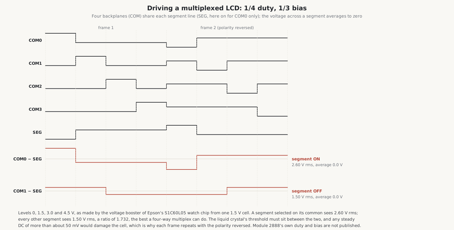
The figure shows the common scheme for watches, 1/4 duty and 1/3 bias: four commons, and four voltage levels made from the cell by the chip’s own voltage booster. Epson’s S1C60 watch chip, for example, makes 1.5, 3.0 and 4.5 V from a single 1.5 V cell with one external capacitor. A segment that is on sees 2.60 V rms; one that is off sees 1.50 V rms. The ratio, 1.73, is the best that four-way multiplexing can give, and the liquid crystal has to be mixed so that it switches between those two voltages, which is why watch displays are multiplexed only a few ways, and why contrast suffers in the cold. Module 2888’s own duty and bias are not published.
4.3 The keypad
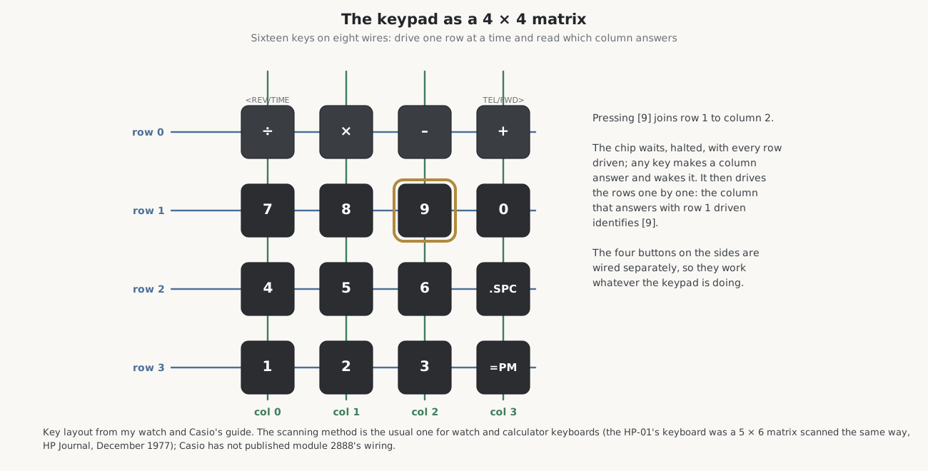
Sixteen keys sit below the display. Inside, they are almost certainly a matrix of four rows and four columns, so that eight wires serve sixteen keys: pressing a key joins its row to its column, and the chip finds which key by driving the rows in turn and reading which column answers. The HP-01 of 1977 scanned its 28 keys the same way, as a “five-column, six-row matrix”, HP’s engineers wrote, with the start address of each key’s program in the chip’s memory given by its row and column.
Getting keys through a watch case without letting in water and dust was the first engineering problem of the calculator watch. Casio’s British patent GB 2,062,304, filed in 1980 with a Japanese priority of October 1979, shows its answer: holes through the case in a matrix, an elastic sheet outside the case carrying conductive bodies that pass through the holes onto contacts on the circuit board, and a screwed-on plate with a window for each key top, the edge of the sheet sealing the case. The DBX-100 of 1988 used a printed membrane: two plastic films, one carrying the contacts and the other sixteen conductive ovals that bridge them when a key is pressed. The rubber key mat over it, its owner reported, had crumbled with age.
The four buttons on the sides of my watch, A, B, C and L, are wired separately, which is why the light works whatever the keypad is doing. Casio’s guide adds that the keypad is disabled while the light is on (p. 4).
4.4 The quartz crystal
The watch keeps time with a quartz crystal vibrating 32,768 times a second: a tiny tuning fork of quartz, cut and etched so that it rings at that frequency when an alternating voltage is applied, sealed in a metal can or a ceramic package. Volume 5 explains the number, how the chip divides it down to seconds, and how the crystal’s rate shifts with temperature.
4.5 Light and the auto light switch
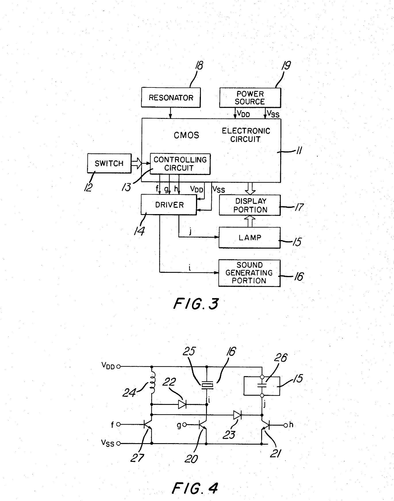
Older Casio Illuminators lit the display with an electroluminescent (EL) panel, a thin sheet of phosphor between two electrodes that glows green-blue when driven with alternating current at high voltage. Module 2888 does not: its guide says the display “is illuminated by an LED (light-emitting diode) and a light guide panel” (p. 4), a small LED at the edge of a clear plastic plate that spreads its light behind the display. An LED runs directly from a 3 V lithium cell. An EL panel needs around 100 volts, which a watch has to make from its cell with a coil. Seiko’s patent US 4,529,322 of 1985 used one coil for both the lamp and the buzzer, boosting a 1.57 V cell to about 100 V for the lamp at 1,024 Hz and 10 to 30 V for the buzzer, and a Timex patent of the same year, US 4,527,096, drove a 2 cm² lamp at 60 to 100 V peak to peak. When Casio replaced EL with LED in a later G-Shock module, the stated battery life rose from five years to ten.
The auto light switch lights the display when the wrist is held level and then turned towards the face by more than 40°. The guide gives away that it is mechanical: “You may notice a very faint clicking sound coming from the watch when it is shaken back and forth. This sound is caused by mechanical operation of the auto light switch” (p. 4). It is a tilt switch with a moving part, perhaps a ball or a small pendulum; Casio does not say which. Because it can fire whenever the arm moves, the watch turns it off by itself after about six hours.
4.6 The buzzer
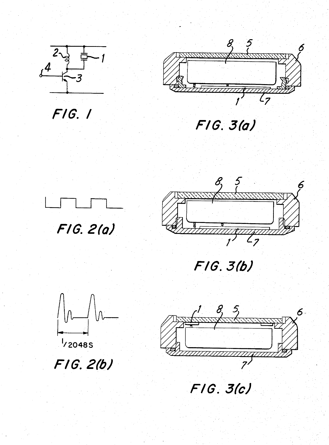
The alarms, the hourly signal and the key beep come from a piezoelectric buzzer: a thin ceramic disc bonded to a metal plate, which flexes when a voltage is applied. Driven with a square wave at a few thousand hertz, it sounds a tone, and coupled to the case back, the whole back becomes its sounding board. Seiko’s patent US 4,526,477 of 1985 describes a 20 mm disc 0.2 mm thick, notes that the back of a watch resonates at about 4 to 10 kHz depending on its thickness and fit, and drives its buzzer at tones divided down from the crystal, 32,768 ÷ 12 and 32,768 ÷ 15 Hz. Early designs needed a step-up coil to reach about 10 V from a 1.5 V cell. Watch chips such as Epson’s S1C60 can instead drive the two sides of the disc in opposition, which from a 3 V lithium cell gives 6 V peak to peak with no coil; whether module 2888 has a coil is not known. In the DBX-100 the buzzer sat behind the keypad, touched by a spring.
4.7 The cell
The face of my watch says 10 Year Battery. The cell, according to Casio’s parts list, is a CR2025: a lithium–manganese dioxide coin cell 20 mm across and 2.5 mm thick, giving 3 V and holding about 163 mAh, by Energizer’s datasheet. Ten years from 163 mAh means an average current of under 2 µA, for everything. How a watch manages that is the subject of the next volume.
Sources
- Casio, Operation Guide 2888 (MO0407-EA, 2004), p. 4 (light, auto light switch, keypad).
- Core Electronics forum, “Casio DBX-100 repair attempt” (2023); Zeptobars, “Casio F-91W: OKI quartz watch”.
- Wikipedia, “Twisted nematic field effect” and “Elastomeric connector”.
- Epson, S1C60N05 datasheet (LCD drive levels and booster, piezo outputs).
- Patents: Casio GB 2,062,304, “Key input device for electronic timepiece calculator”; Seiko US 4,529,322 and US 4,526,477; Timex US 4,527,096; Suwa Seikosha US 4,129,983 (watch LCD mixtures); US 4,110,967 (static and matrix LCD drive).
- Hewlett-Packard Journal, December 1977, pp. 2–10 (the HP-01’s keyboard matrix).
- Notebookcheck on Casio’s EL-to-LED module change; Energizer CR2025 datasheet; Casio parts list for the DBC-32.
Comments (0)