VFD Calculators · Volume 2
The Vacuum-Fluorescent Tube
The vacuum-fluorescent tube was invented to get round a patent and a voltage. By the mid-1960s the Japanese calculator makers were buying Nixie tubes by the hundred thousand, paying royalties to Burroughs on every one, and building high-voltage supplies to light them. A small company in Ise, Mie Prefecture, founded for the purpose, gave them a display that lit at 25 volts, could be made in Japan without a Burroughs licence, and could be driven by the same chips that did the arithmetic. Within five years it was the standard calculator display in Japan, and the company was making a million tubes a month.
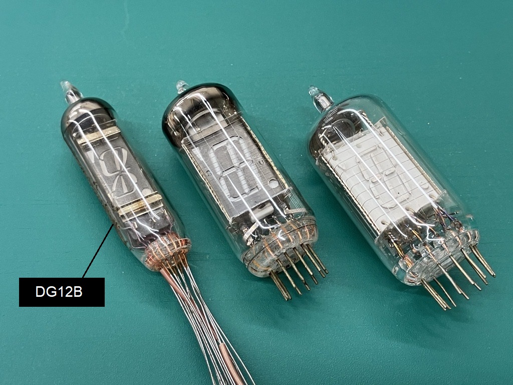
2.1 Ise Electronics
Tadashi Nakamura was born in Ise City in 1923, trained in electronic engineering at Nagoya, and spent twenty years at Kawanishi Machine Works, later Kobe Kogyo, where he worked on display tubes; his doctoral thesis of 1962 was titled Fundamental Problems in Display Tubes. When Fujitsu took over Kobe Kogyo and stopped his project for a transistorised portable colour television, he left to start his own firm.
The push came from Sharp. Tadashi Sasaki of Hayakawa Electric, as Sharp was then called, encouraged Nakamura to develop a low-voltage display for calculators. Sharp’s first electronic calculator, the CS-10A of 1964, used Burroughs Nixie tubes running at about 170 volts, and the Japanese makers paid Burroughs a royalty of 15 per cent, about 45 cents on a tube that sold for 3 dollars. Ise Electronics Corporation (伊勢電子工業) was founded in September 1966 with twelve employees and ¥20 million of capital. Masao Okubo of Japan Electronic Materials lent a laboratory in Kyoto, and the first prototypes are said to have been finished in about two months.
The dates that follow come from the IEEE Milestone proposal, which reproduces the period press reports:
Table 1 — The dates that follow come from the IEEE Milestone proposal, which reproduces the period press reports
| Date | Event |
|---|---|
| September 1966 | Ise Electronics founded |
| March 1967 | Prototype samples delivered to Hayakawa Electric; Japanese priority date of the basic patent |
| 29 May 1967 | Electronics magazine describes the tube, the first public report |
| 17 and 21 July 1967 | Japanese trade papers report a “character display at about 25 volts” and Ise’s plan to mass-produce the “Digitron” |
| September 1967 | Hayakawa adopts the tube for its calculators; mass production begins |
| December 1967 | The Sharp CS-16A, the first calculator with a VFD, goes on sale |
| January 1968 | The Nikkan Kogyo Shimbun names the tube one of its ten new products of the year |
Production went from about 3,000 tubes a month in 1967 to 30,000 a month in 1968 and about a million a month in the 1970s.
The technical keys, in the proposal’s account, were four: a zinc-oxide phosphor that glows under low-energy electrons; very fine cathode wire, supplied by Japan Electronic Materials; phosphor work with Dai Nippon Toryo and Professor Takagi of Shizuoka University; and the decision to look at the phosphor from the cathode side, through the filament and grid, rather than through the phosphor as in a cathode-ray tube. The proposal calls this the “Columbus’ egg” of the design: obvious once seen.
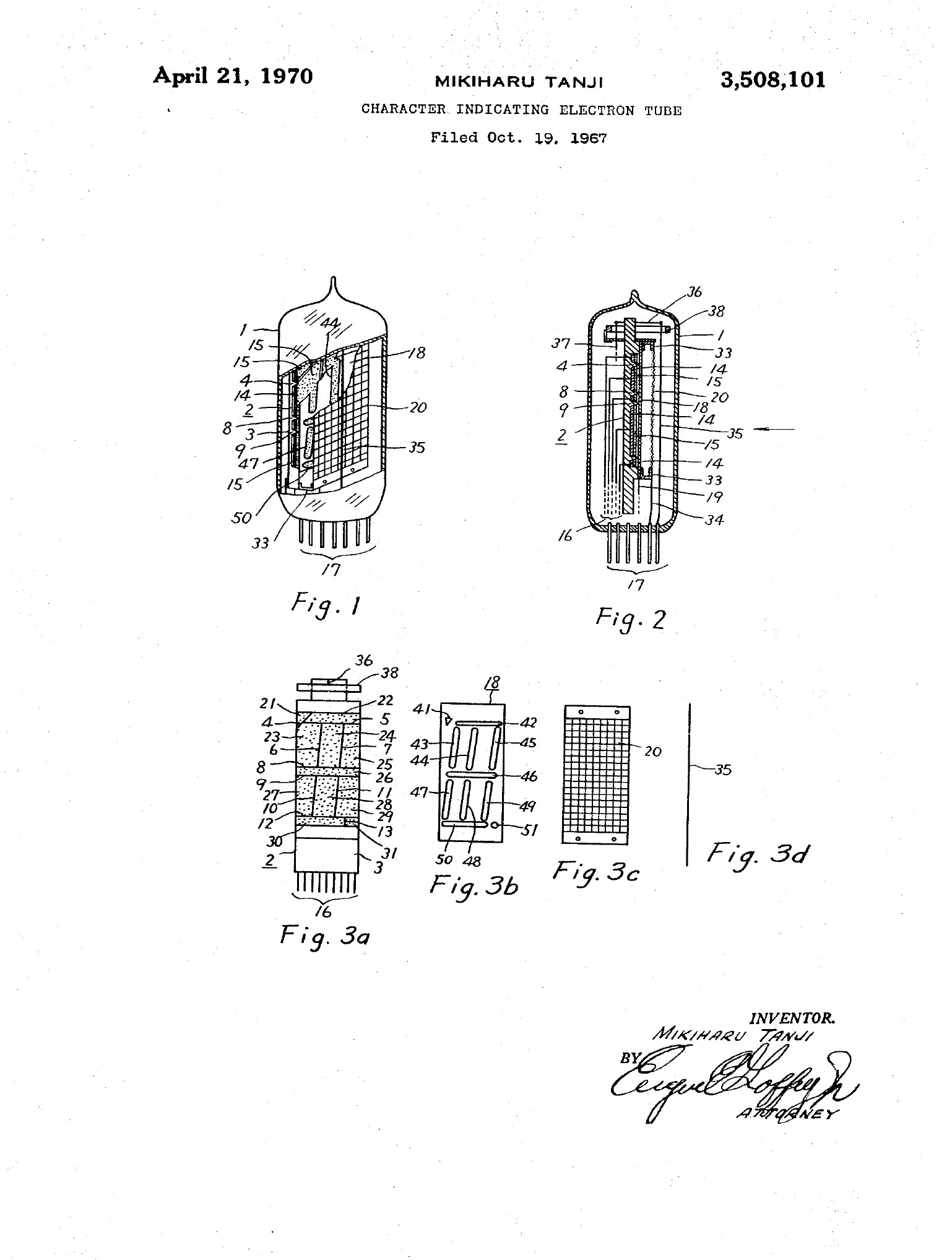
Who invented it is not quite settled. Nakamura founded the company and led it, and the Milestone plaque names him. One source cited in the IEEE review credits Masao Okubo with the invention and Nakamura with its mass production, and the basic United States patent names neither: its inventor is Mikiharu Tanji of Ise Electronics.
2.2 The basic patent
Tanji’s patent, US 3,508,101, filed on 19 October 1967 and granted on 21 April 1970, describes the tube almost exactly as it was made for the next two decades. Its key passages:
- the cathode is “a single fine wire of the order of 30–50 microns”, stretched in front of “a very fine mesh type grid”;
- about 0.8 volt is applied to the cathode “to heat it to a dark red color”, and about +25 volts to the grid and to the selected anode segments;
- if the grid is brought to the potential of the cathode or below, “the cathode emission cannot reach the anode”;
- a getter ring at the top of the tube removes residual gas;
- and the operating voltage of about 25 volts “is of the order of that utilized in the operation of semi-conductor and integrated circuits”.
The last point was the whole commercial case. The patent names the Nixie tube, with its high voltage, as the thing it improves on.
2.3 How the tube is built
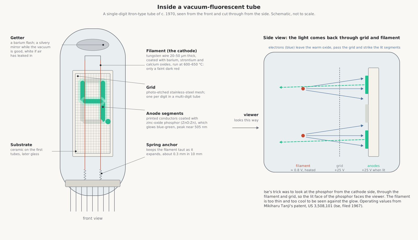
The filament (cathode). A very fine tungsten wire, 20 to 50 micrometres thick, coated with the carbonates of barium, strontium and calcium. In the vacuum the carbonates are baked into oxides, as in an ordinary valve, and the oxide coating gives off electrons at 600 to 650 °C. At that temperature the wire glows only a faint dark red, too dim and too thin to be seen against the lit segments. One end is fixed and the other is held by a small spring, because a 10 mm filament grows about 0.3 mm as it heats; if the spring weakens, the wire sags and can touch the grid. Single-digit tubes have one or two filament wires; a long multi-digit tube has several in parallel.
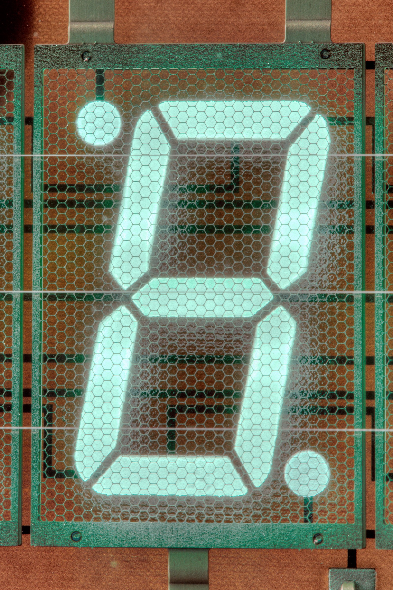
The grid. A mesh of stainless steel, photo-etched into a fine lattice or a sheet of hexagonal holes. It sits between the filament and the anodes and decides whether electrons reach them. In a multi-digit tube each digit has its own grid.
The anodes. The segments of the figure, printed as conductors on a substrate and coated with phosphor. Early tubes used a ceramic base with ridges between the segments; later ones are thick-film printed on glass, with the wiring, an insulating layer and the anodes in layers and graphite-filled holes joining them.
The phosphor. Zinc oxide with an excess of zinc, ZnO:Zn. It is unusual in two ways: it glows strongly under electrons of only a few tens of volts, and it conducts just enough (about 10³ to 10⁴ ohm-centimetres) to bleed away the charge that the electrons would otherwise build up on its surface. Its light is a broad blue-green band peaking near 505 nm. Other low-voltage phosphors of the time gave only 5 to 20 per cent of its brightness, so for the whole calculator era VFDs were green. Its response is fast: Ise measured rise and fall times of about 10 microseconds.
The envelope. Glass, sealed with a low-melting glass frit and evacuated through a small exhaust tube that is then pinched off; the tip is often visible. Inside the face glass of later tubes is a transparent conductive coating of tin oxide (NESA) that stops static charge building up on the glass. A getter, a small ring of barium, is flashed by heating after sealing and deposits a silvery mirror on the inside of the glass; it goes on absorbing stray gas for the life of the tube. If air ever gets in, the mirror turns white.
Manufacture. Ise’s 1976 paper on its flat multi-digit tube gives the sequence: print the glass base plate, paint the phosphor, weld in the filaments and getter, seal with frit, evacuate, flash the getter, age the tube, and test it.
2.4 How a segment lights
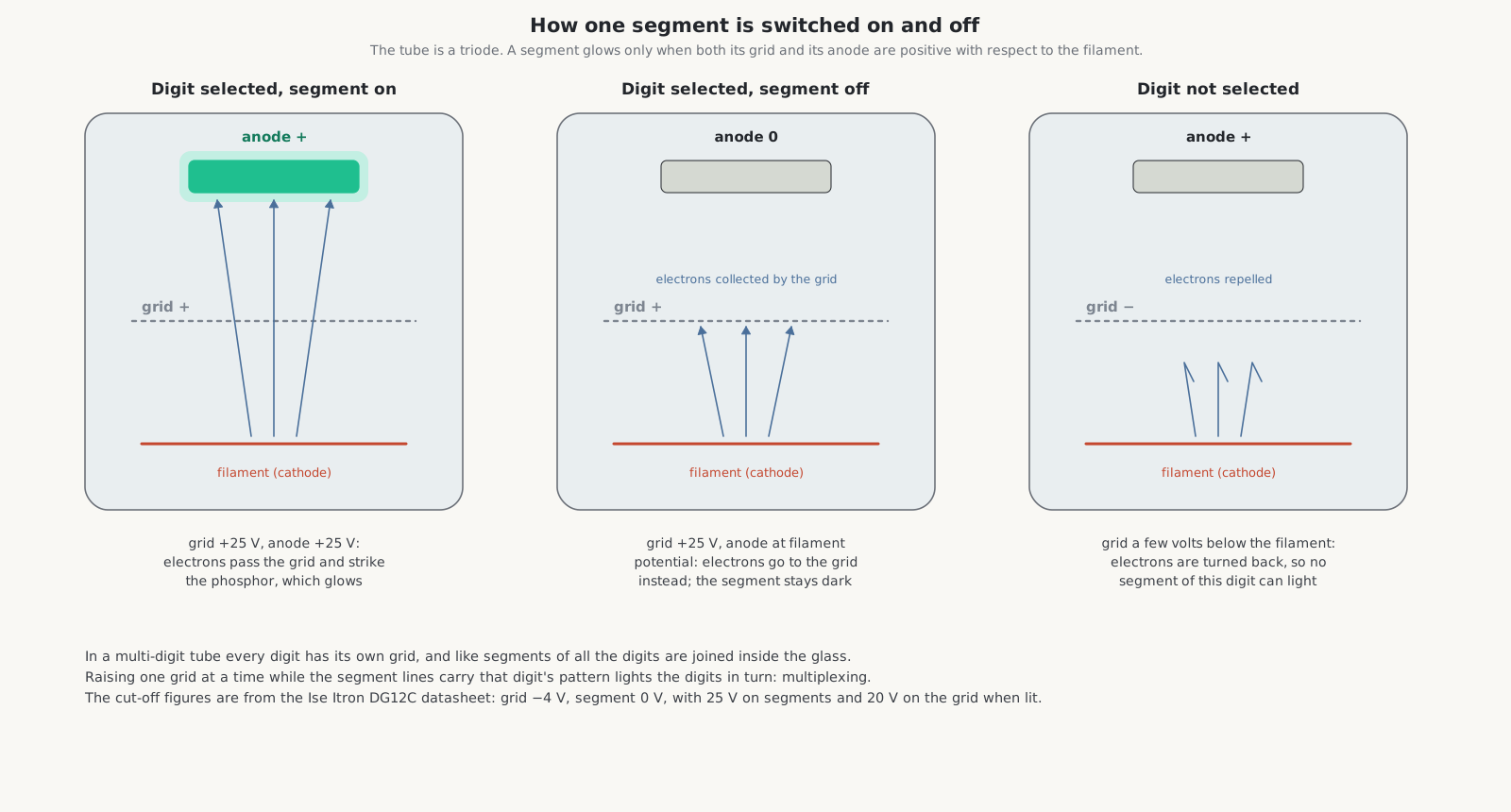
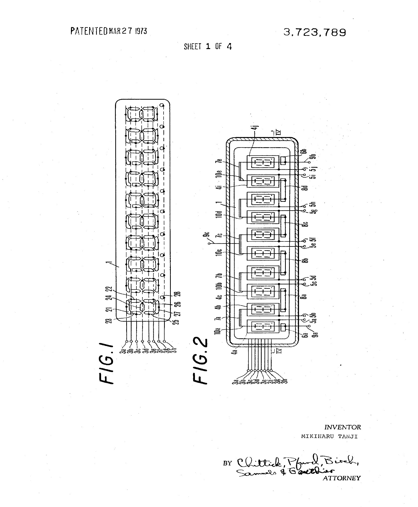
The tube is a triode, and a segment glows only when both its grid and its anode are positive with respect to the filament. Ise’s 1983 paper puts it plainly: “the grid and anode should be simultaneously positively charged for the emission of light.” That two-key rule is what makes the tube so easy to multiplex. In a multi-digit tube every digit has its own grid, and the same segment of every digit is wired to one common line inside the glass. Raise one grid at a time while the segment lines carry that digit’s pattern, and the digits light one after another, fast enough that the eye sees them all at once. The display volume shows how.
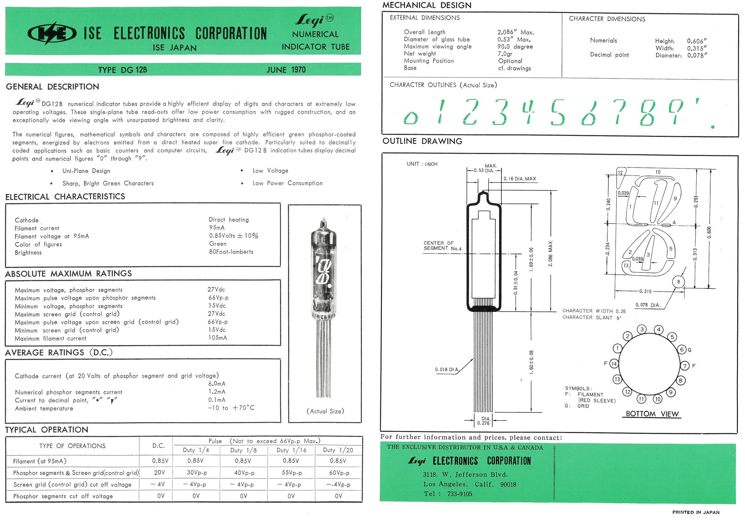
To turn things off reliably, the “off” levels sit a little below the filament. The Ise DG12C datasheet of 1968 gives the figures for a single tube: segments 25 V and grid 20 V when lit; segment cut-off 0 V and grid cut-off −4 V, both measured from the filament.
2.5 What sets the brightness
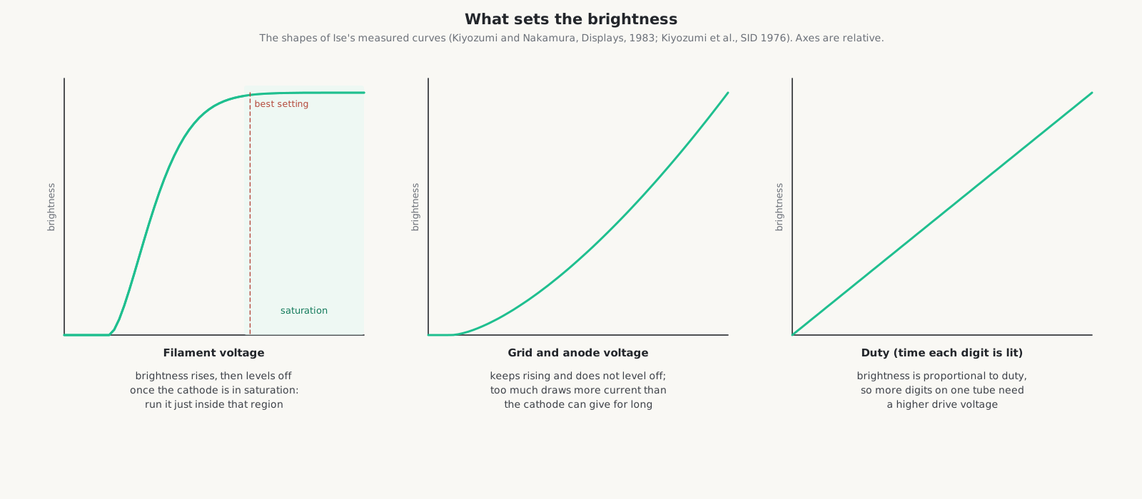
Ise’s engineers published the curves in 1976 and 1983:
- Filament voltage. As the filament warms, emission, brightness and current rise together, then level off once the cathode is in saturation. The right setting is “the lowest possible value in the saturation region”. Below it the brightness follows every ripple in the supply; above it the filament runs hot and its life is shortened for nothing. The repair volume comes back to this, because it is the physics behind “rejuvenating” a tired tube.
- Grid and anode voltage. “Except in rare special cases” the two are made equal. Brightness keeps climbing as they rise and does not level off, but the current drawn from the cathode climbs too, and past its limit the cathode is damaged.
- Duty. In a multiplexed tube each digit is lit only part of the time, and brightness is proportional to that fraction. A tube with more digits needs a higher drive voltage for the same brightness, which is why pocket tubes with eight or nine digits ran at 25 to 30 volts and desk tubes with twelve or more at 40 to 50.
The data for the first tubes:
Table 2 — The data for the first tubes
| Tube | Kind | Filament | Grid and segments, lit | Cut-off | Other | Source |
|---|---|---|---|---|---|---|
| Ise Itron DG12C (1968) | single digit, 7 segments, point and comma | 0.85 V ±10 %, 95 mA | segments 25 V, grid 20 V | grid −4 V, segment 0 V | 80 foot-lamberts; 10 mA cathode current; tube 53 × 13 mm, figures 10.8 × 7.2 mm | Ise datasheet |
| Ise Itron DG-19 (1968) | single digit | 1.6 V ±10 %, 95 mA | segments 25 V, grid 20 V | — | segments rated to 50 V pulsed | Ise datasheet |
| Ise flat 9-digit tube (1976) | multi-digit, for handhelds | 2.7 V AC | 24 V peak-to-peak, each digit lit 1/12 of the time | — | the whole tube used 39.6 mW | Kiyozumi et al., SID 1976 |
| Soviet IV-4 | single, 18 segments | 2.2–2.9 V, 50 mA | 25–27 V static, 50–70 V pulsed | — | life 3,000 h | lampes-et-tubes.info |
2.6 From one digit to sixteen
The tube changed shape three times in its first ten years, and the changes can be read in the calculators:
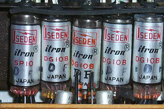
- Single-digit tubes (1967–73). One figure per glass envelope, about 12 mm across, mounted in a row on flying leads or in sockets: the DG12B in the Sharp CS-16A, the DG10B in the QT-8D, the DG10L in the EL-8.
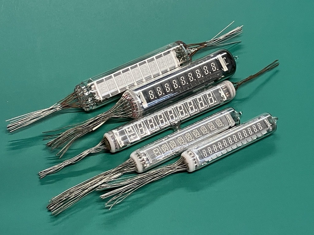
- Round multi-digit tubes (from 1972). Several digits in one long glass tube, each with its own grid, the segments joined inside. The IEEE proposal says that “by 1972, each company shifted to 12mm round glass multi-digit tubes for handheld calculators”; the Casio Mini CM-601 of February 1973 was changed to one. Sharp’s 1974 tubes had leads at both ends so that nine digits would fit.
- Flat tubes (from about 1971–72). The base plate is one wall of the envelope, the anodes printed on it, and the digits seen through a flat front glass. Ise made a multi-digit metal tube with a flat window in 1971 and solved the problems of the all-glass flat tube by 1972. Ise’s patents US 3,723,789 (filed 1970) and US 3,786,295 (filed 1972) cover the flat multi-digit tube and its printed anode plate. By 1975 flat modules with a dozen digits and their connector pins along the edge were in every kind of desk machine.
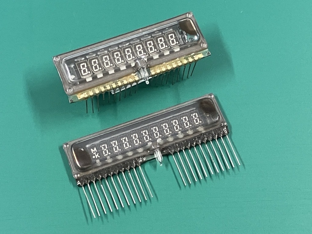
2.7 The other makers, and what they called it
Ise licensed its patents to NEC and Futaba, and both signed production agreements with it.
- Futaba (双葉電子工業), founded in 1948 in Mobara, Chiba, to make radio valves, began making display discharge tubes for calculators in January 1968, gave up valves entirely for fluorescent tubes in May 1970, and became one of the two largest VFD makers in the world. It announced its withdrawal from the business in 2020.
- NEC made calculator tubes at its Kagoshima works under the LD- type numbers, and called its displays FIP, for fluorescent indicator panel.
- Toshiba also made calculator tubes, used by Casio among others.
The names are a tangle. The Japanese press of 1967 called Ise’s tube the Digitron; Ise’s own trade name became Itron, and its tubes are marked ISEDEN. Casio called the display in its own manuals a “Digitron tube”. NEC used FIP. Collectors and engineers now say VFD, or in Japanese 蛍光表示管, fluorescent display tube.
The Ise tube was not the first vacuum-fluorescent device of any kind. Philips’ DM160 of 1959 was a small single-element indicator working on the same principle. The Ise tube of 1967 was the first numeric one and the first to be made in quantity.
Table 3 — The other makers, and what they called it
| Maker | Tube | Kind | Used in |
|---|---|---|---|
| Ise | DG12B, with SP12A sign tube | single digit | Sharp CS-16A (1967); Burroughs C3260 / Sharp EL-160 (1971) |
| Ise | DG10B, with SP10 | single digit, eight segments, half-height zero | Sharp QT-8D and QT-8B; Burroughs C3146 |
| Ise | DG10L, with SP8A | single digit | Sharp EL-8 |
| Ise | DP60A | six digits, one envelope | Casio Mini CM-602 (1973) |
| Ise | DP89A | eight digits, metal-backed | Rockwell 203 (1974) |
| Ise | FG95A, FG125A2 | flat panel | Qualitron 1438, Adler 108T (1975) |
| Futaba | DG10Q1, DG10FL, DG10R1 | single digit | Sharp EL-811A, Casio AS-8S, Sanyo ICC-805 |
| Futaba | 9-ST-08A, 9-ST-10, 9-ST-12 | nine digits | Sharp EL-8109, National Semiconductor 200, Prinztronic SC4001M |
| Futaba | 13-MR-01, 13-MT-26 | thirteen-digit module | Olympia CD401A, Victor Medalist 204 |
| NEC | LD8035 | single digit | Casio Mini (1972), Toshiba BC-0802 |
| NEC | LD8120, LD8124, LD8126 | multi-digit | Casio Personal-8, fx-20, fx-101 |
| Toshiba | E6525 | eight digits | Casio fx-10 (1974) |
The table is gathered from John Wolff’s and Brent Hilpert’s pages, Rick Bensene’s museum and the IEEE proposal. No catalogue of Ise, Futaba or NEC calculator tubes has been found, so it is a sample, not a list.

2.8 Soviet tubes
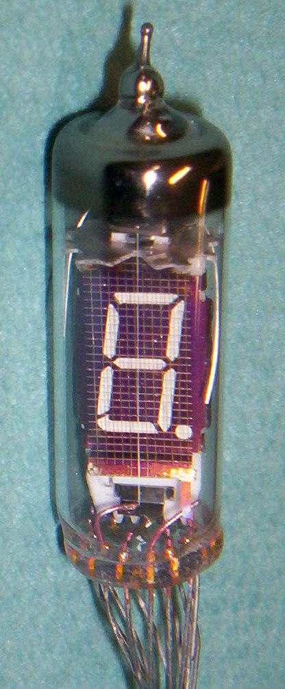
The Soviet Union made its own vacuum-fluorescent tubes in quantity, under the ИВ (IV) prefix for single digits and ИЛЦ (ILC) for multi-digit types, and they are the tubes most hobbyists build with today. The IV-6 is a single seven-segment digit; the IV-18 an eight-digit tube; the ILC1-8 and ILC2-12 the calculator modules of the Elektronika B3- and MK- series. Their story belongs with the Soviet calculators.
2.9 Honours
Nakamura received the Society for Information Display’s Special Recognition Award in 1979 and its Karl Ferdinand Braun Prize, shared with Kentaro Kiyozumi, in 1991. Ise came under Nippon Toki, now Noritake, which took a stake in 1974; it was renamed Noritake Itron in 2002, became a wholly owned subsidiary in 2006, and was renamed Noritake Ise in 2025. On 4 November 2025 the IEEE dedicated Milestone No. 289, “Vacuum Fluorescent Displays, 1967”, at the Noritake Ise works in Mie Prefecture. Its plaque says that VFDs “were first commercialized in 1967 by Tadashi Nakamura”, and that they replaced Nixie tubes and transformed calculators.
The primary documents are in the Library: Tanji’s basic patent, the multi-digit tube patent, Ise’s papers of 1976 and 1983, the Electronics report of May 1967, the Itron DG-12C datasheet and the Hitotsubashi University case study of Ise Electronics, in Japanese.
Comments (0)