VFD Calculators · Volume 8
Building One Today
A fluorescent-display calculator is one of the friendliest vintage displays to build with. The tubes run on 25 to 50 volts rather than the Nixie’s 170, so the supply is a small boost converter and nothing on the board can give more than a tingle. Soviet tubes are cheap and plentiful, and modern driver chips do in one package what the 1970s calculators did with a row of transistors. The theory volumes give every rule a build needs; this volume shows what others have made and the parts a new one would use.
8.1 Projects others have built
oskar2517’s IV-12 calculator. Five Soviet IV-12 single-digit tubes, an Arduino Nano, a custom board for the multiplexing and the power supply, and a case of laser-cut plywood with walnut veneer. It was featured on Hackaday, the Arduino blog and in HackSpace magazine in 2024. It has no decimal point.
shiura’s Casio Mini. A Casio Mini CM-602 of 1973 that could not be saved was given a second life: its case and keys became an RPN calculator, and its original six-digit fluorescent tube moved into a clock synchronised over Wi-Fi by an ESP32. The tube’s filament, about 8 Ω, is fed from 5 V through about 40 Ω, roughly five times its own resistance, and set by eye; Mitsubishi M54564P source drivers switch 25 V from 3.3 V logic without pull-up resistors. The code and case files are on GitHub.
Sciter_’s single-AA clock. A clock built from a recycled calculator display that runs from one AA NiMH cell, with an ATmega328P and an HV5812 driver; the filament takes about half a watt. Hackaday featured it in June 2026.
MyVFD. A nine-digit information display built round a Futaba 9-ST-08A tube from a 1970s calculator, with an ESP32, a ULN2803 driver array, about 3 V on the filament and a step-up converter for the grids. The builder notes that the 9-ST-08A “is too old, so it’s almost impossible to find the datasheet”: the pinout was worked out by experiment.
Commercial IV-18 clocks are common, and at least one has offered a calculator function. No open-source VFD calculator kit, RPN or otherwise, was found.
8.2 What a build needs
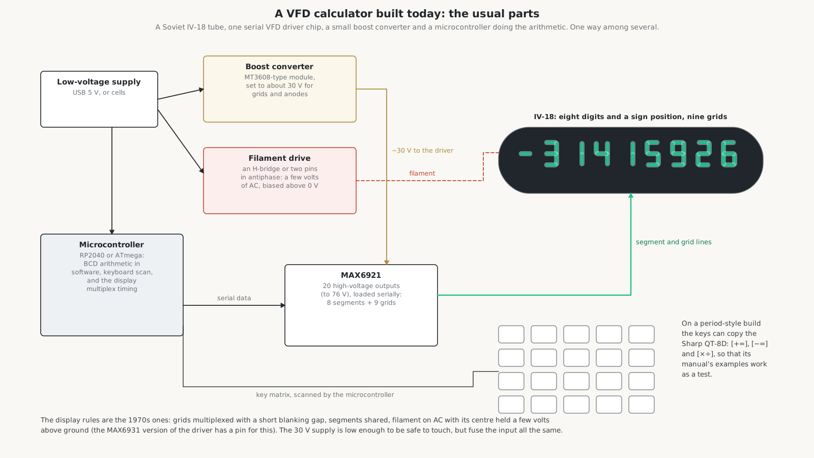
A tube. The Soviet IV-18 (ИВ-18) is the obvious choice: eight digits and a sign position in one long glass tube, nine grids, sold cheaply as new old stock. Sources disagree on its filament: one gives 5 V at 85 mA, another 2.4 V; measure the resistance and bring it up slowly. The single-digit IV-6, IV-12 and IV-11 allow any number of digits and any layout. A tube salvaged from a dead calculator is the authentic choice; expect to map its pins by experiment.
A supply for the grids and anodes. A small boost module of the MT3608 type, set to 25 to 30 volts, is enough for a nine-digit multiplexed tube; the XL6009 type reaches about 50 V for longer tubes or brighter displays. The Valve Wizard’s IV-18 clock adds a voltage doubler for a fixed 40 V.
A filament drive. Use AC, for the reasons in the display volume: a DC filament gives a visible slant of brightness along a long tube. Simple ways to make it: two microcontroller pins driven in antiphase into an H-bridge, giving a square wave of a few volts (as MyVFD does); a small transformer; or, as Texas Instruments did in the TI-1025, a square wave at a kilohertz or so. A DC filament through a series resistor works for a short tube. In a positive-supply hobby circuit the filament’s centre must sit a few volts above ground, so that a driver output at 0 V is below the filament and turns its grid or segment off.
A driver.
- The MAX6921, from Maxim (now Analog Devices), has twenty outputs rated to 76 V, loaded through a four-wire serial interface at up to 5 MHz from 3 to 5.5 V logic, and each output sources up to 40 mA. Eight segments and nine grids for an IV-18 fit in its twenty outputs. Its sister, the MAX6931, adds a pin for the filament bias.
- The HV5812, from Microchip, has twenty outputs rated to 80 V.
- A ULN2803 with pull-up resistors, or source drivers such as the M54564P, are cheaper alternatives. Optocouplers driven from 74HC595 shift registers also work.
A brain. Any microcontroller. A calculator’s arithmetic is a few hundred lines of code. For authenticity, write it as the 1970s chips worked: numbers in binary-coded decimal, digit by digit, with the same truncation and overflow behaviour as the machine being imitated. The display loop is the multiplexing of the display volume: raise one grid, set the segments, wait, drop the grid, leave a short blanking gap, move to the next digit, and repeat the whole row a few hundred times a second.
A keyboard. A key matrix scanned by the microcontroller. For a period feel, copy a real machine: the Sharp QT-8D’s [+=], [−=] and [×÷] keys make the examples in its manual, in the operating volume, a ready-made acceptance test.
A case and a filter. A green or blue-green filter in front of the tube deepens the colour and hides the filament’s faint glow, exactly as on the originals.
8.3 A rough budget
Table 1 — A rough budget
| Item | Cost |
|---|---|
| IV-18 tube, new old stock | $10–25 |
| Boost converter module | $2–5 |
| MAX6921 or HV5812 driver | $5–15 |
| Microcontroller board | $5–20 |
| Key switches and keycaps | $20–50 |
| Circuit board, resistors, connectors | $15–30 |
| Total | about $60–150, plus the case |
These are rough estimates, not quotations.
8.4 Safety
Thirty volts DC from a boost module is low enough not to be dangerous to touch, which is a large part of the charm of building with fluorescent tubes. Fuse the low-voltage input all the same, because a shorted converter can overheat, and treat any glass tube with flying leads gently: the leads break where they leave the glass.
8.5 A reproduction of an original?
Nobody appears to have reproduced a period VFD calculator. A faithful copy of a Sharp EL-8, with eight single-digit tubes in a row behind a green window and the QT-8D’s keyboard and arithmetic, would be a practical project: the tubes can be Soviet IV-6s, the logic one microcontroller, and the supply a single boost module.
Comments (0)