Flight Computers · Volume 5
The Mathematics of Flight
Every function on my E6B’s menu is a formula a pilot could, in principle, work by hand. This volume sets them out: the wind triangle, the airspeeds, the altitudes, time, distance and fuel, and weight and balance. Each worked example comes from the FAA’s handbooks or Sporty’s manual and has been recomputed from the exact formulas; where the E6B, a rule of thumb or a slide rule gives a slightly different answer, the difference is shown.
5.1 The wind triangle
An aircraft flies through the air, and the air itself moves. Three vectors describe a flight:
- the air vector: the direction the aircraft points (its heading) and its speed through the air (its true airspeed, TAS);
- the wind vector: the direction the wind blows from and its speed;
- the ground vector: the direction the aircraft actually travels over the ground (its course or track) and its ground speed (GS).
The ground vector is the sum of the other two. Drawn to scale for one hour of flight, the three make a triangle, which is why pilots call it the wind triangle.
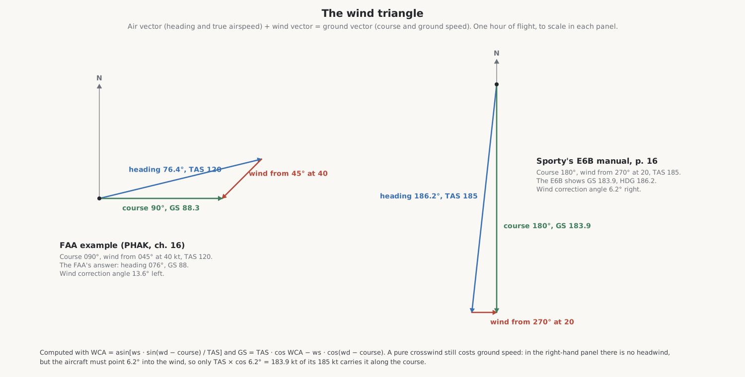
To fly a chosen course, the pilot needs the heading and the ground speed. If the wind blows from direction W at speed w, the course is C and the true airspeed V, the wind correction angle and ground speed are
WCA = arcsin[ w · sin(W − C) / V ], GS = V · cos(WCA) − w · cos(W − C),
and the heading is the course plus the correction angle. In the FAA’s example in its Pilot’s Handbook of Aeronautical Knowledge (chapter 16), a course of 090° with a wind from 045° at 40 knots and a true airspeed of 120 knots needs a heading of 076° and gives a ground speed of 88 knots; the formulas give 076.4° and 88.3. Sporty’s manual (p. 16): a course of 180°, a wind from 270° at 20 and a TAS of 185 give HDG 186.2 and GS 183.9, exactly what the formulas give. And the problem on the cover of my E6B’s manual, a wind from 315° at 21, a course of 045° and 165 knots, works out to a heading of 37.69° and a ground speed of 163.66; the cover shows 37.7 and 163.6.
The second example shows something the slide rule makes easy to forget. The wind there is a pure crosswind, blowing from straight off the right, with no headwind at all, and still the ground speed is less than the airspeed: the aircraft must point 6.2° into the wind, and only the component of its speed along the course, 185 × cos 6.2° = 183.9, carries it towards its destination.
The same triangle can be solved the other way. Given the heading, airspeed, course and ground speed actually flown, the wind is whatever closes the triangle: Sporty’s WIND example (pp. 21–22), a course of 355° and a heading of 350° at 200 knots through the air and 170 over the ground, gives a wind from 324° at 34 knots.
5.1.1 Crosswinds on a runway
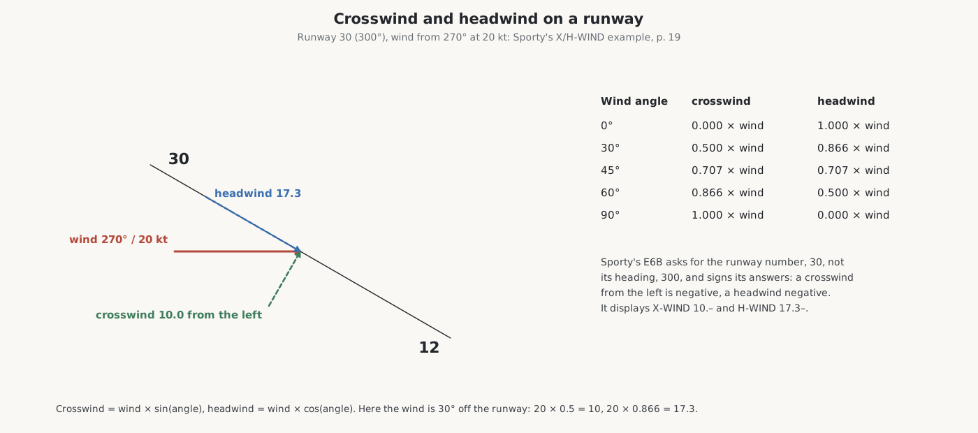
For take-off and landing what matters is the wind’s component across the runway and along it: crosswind = wind × sin(angle), headwind = wind × cos(angle). Sporty’s example (p. 19), a wind from 270° at 20 knots on runway 30 (300°), is 30° off the runway: a crosswind of 10 knots and a headwind of 17.3.
5.2 Airspeeds
The airspeed indicator measures the push of the air, not speed through it, and the FAA’s handbook (chapter 8) distinguishes four speeds:
- indicated airspeed (IAS), read from the dial;
- calibrated airspeed (CAS), corrected for errors in the instrument and its installation, from a table in the aircraft’s handbook;
- true airspeed (TAS), the actual speed through the air, higher than CAS in thin air;
- Mach number, the speed as a fraction of the speed of sound, which depends only on the air’s temperature.
The rule of thumb adds 2 per cent to the calibrated airspeed for every thousand feet of altitude. The exact conversion uses the pressure and temperature of the air and allows for its compressibility at speed. Sporty’s PLAN TAS example (pp. 15–16), a calibrated airspeed of 200 knots at a pressure altitude of 10,000 feet and 2 °C, gives a true airspeed of 234.5 knots exactly, Mach 0.363; Sporty’s E6B shows 234.7 and 0.36; the rule of thumb gives 240, nearly six knots too fast.
My E6B has two versions of each airspeed and Mach function. PLAN TAS and PLAN M# take the true outside air temperature, as a forecast gives it. ACT TAS and ACT M# take the temperature indicated on the aircraft’s thermometer, which reads high at speed because the air is compressed and warmed against the probe, and correct for it. The difference is a few knots at light-aircraft speeds and much more at jet speeds.
5.3 Altitudes
An altimeter is a barometer. It shows the height in a standard atmosphere at which the pressure would be what it measures, offset by the altimeter setting the pilot dials in. Two derived altitudes matter for performance:
- Pressure altitude is what the altimeter would read set to the standard 29.92 inches of mercury. The rule of thumb is a thousand feet for each inch of difference; the exact figure near sea level is about 940 feet per inch.
- Density altitude is the height in the standard atmosphere at which the air would be as thin as it is now. Hot, high and humid air is thin, and an aircraft’s engine, propeller and wing all perform as though it were higher. The rule of thumb adds 120 feet for each degree Celsius above the standard temperature for the pressure altitude.
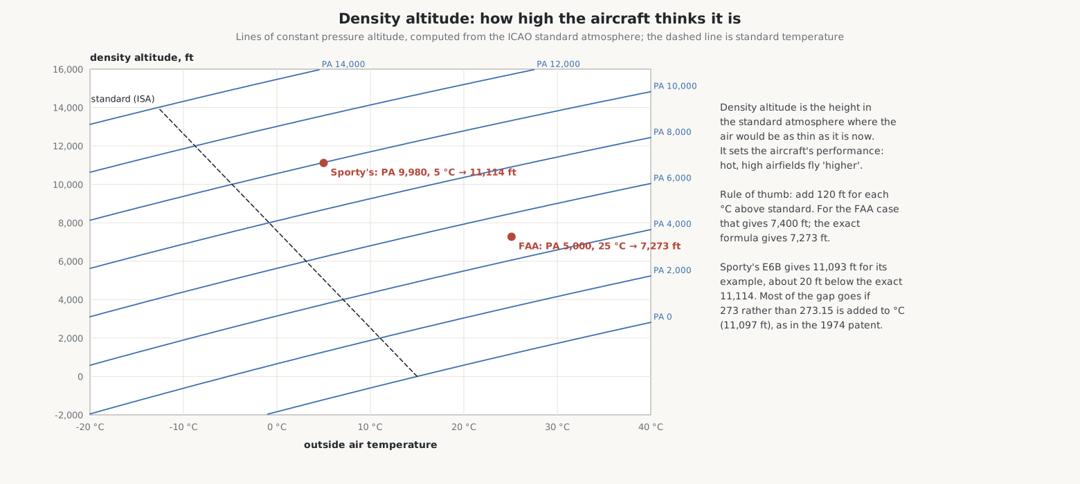
The FAA’s example, a pressure altitude of 5,000 feet with the air 20 °C warmer than standard (25 °C), gives a density altitude of 7,273 feet by the exact formula and 7,400 by the rule of thumb. Sporty’s P-D/ALT example (pp. 14–15), an indicated altitude of 10,000 feet with the altimeter at 29.94 and 5 °C, shows a pressure altitude of 9,980 feet, the rule-of-thumb answer, where the exact standard atmosphere gives 9,983, and a density altitude of 11,093, about 20 feet below the exact 11,114. Most of that small gap disappears if the temperature is converted to kelvin by adding 273 rather than 273.15, as the 1974 patent’s formula does. None of these differences matters to a pilot; they show that every computer, electronic or not, is a set of choices.
5.4 Time, distance and fuel
These are the simplest: distance = ground speed × time, and fuel = burn rate × time. Sporty’s examples:
Table 1 — These are the simplest: distance = ground speed × time, and fuel = burn rate × time. Sporty's examples
| Function | Inputs | Answer |
|---|---|---|
| LEG TIME (p. 17) | 25 nautical miles at 185 knots | 00:08:06 |
| GS (p. 22) | 18 nautical miles in 7 minutes | 154.3 knots |
| DIST FLN (p. 27) | 15 minutes at 185 knots | 46.3 miles |
| FUEL REQ (p. 18) | 3 h 15 min at 14 gallons an hour | 45.5 gallons |
| FPH (p. 23) | 45.5 gallons in 3 h 15 min | 14 gallons an hour |
| ENDUR (p. 28) | 74 gallons at 14 an hour | 05:17:09 |
The E6B works in hours, minutes and seconds as well as decimal hours. Sporty’s manual adds a warning that FUEL REQ “computes fuel consumption only; it does not take required fuel reserves into account”.
5.5 Weight and balance
An aircraft must be loaded so that its weight is within limits and its centre of gravity within a range set by the manufacturer. Each item’s weight multiplied by its arm, its distance from a reference datum, gives its moment; the centre of gravity is the total moment divided by the total weight. Sporty’s WT/ARM example (pp. 30–33) loads an aircraft of 2,467 pounds empty, at an arm of 76.7 inches, with fuel, four people and baggage, to 3,600 pounds with its centre of gravity at 80.39 inches; taking one 170-pound passenger out moves it to 78.67.
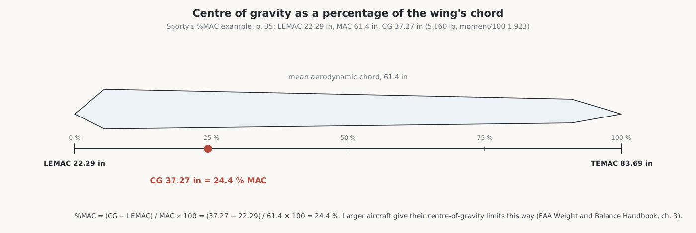
Larger aircraft give the centre of gravity as a percentage of the wing’s mean aerodynamic chord (MAC): the distance aft of the chord’s leading edge (LEMAC), divided by the chord’s length. Sporty’s %MAC example (pp. 35–36): a centre of gravity of 37.27 inches, LEMAC 22.29, MAC 61.4, which is 24.4 per cent of MAC.
Sources
- FAA, Pilot’s Handbook of Aeronautical Knowledge (FAA-H-8083-25C), chapter 16 (navigation and the wind triangle), and chapters 8 and 11; FAA, Weight and Balance Handbook (FAA-H-8083-1B), chapters 3 and 10.
- Sporty’s, Sporty’s E6B Electronic Flight Computer manual, Version 05A (2005), pp. 14–36.
- Patent US 3,979,057 (1976), for its density-altitude formula.
- The exact values are my own calculations with the ICAO standard atmosphere and the standard airspeed formulas.
Comments (0)