Soviet Calculators · Volume 6
Inside the MK-61
The MK-61 and its family, the B3-34, MK-54, MK-56 and MK-52, are among the best-understood calculators ever made, and that is the work not of their makers, who published little about the chips, but of enthusiasts. In 2011 and 2012 Felix Lazarev opened an MK-61, photographed its chips under a microscope, read the contents of their read-only memories from the photographs, diode by diode, and wrote an emulator, emu145, that runs the original microcode. With the factory schematics, his work makes it possible to say how these machines work down to the clock tick.
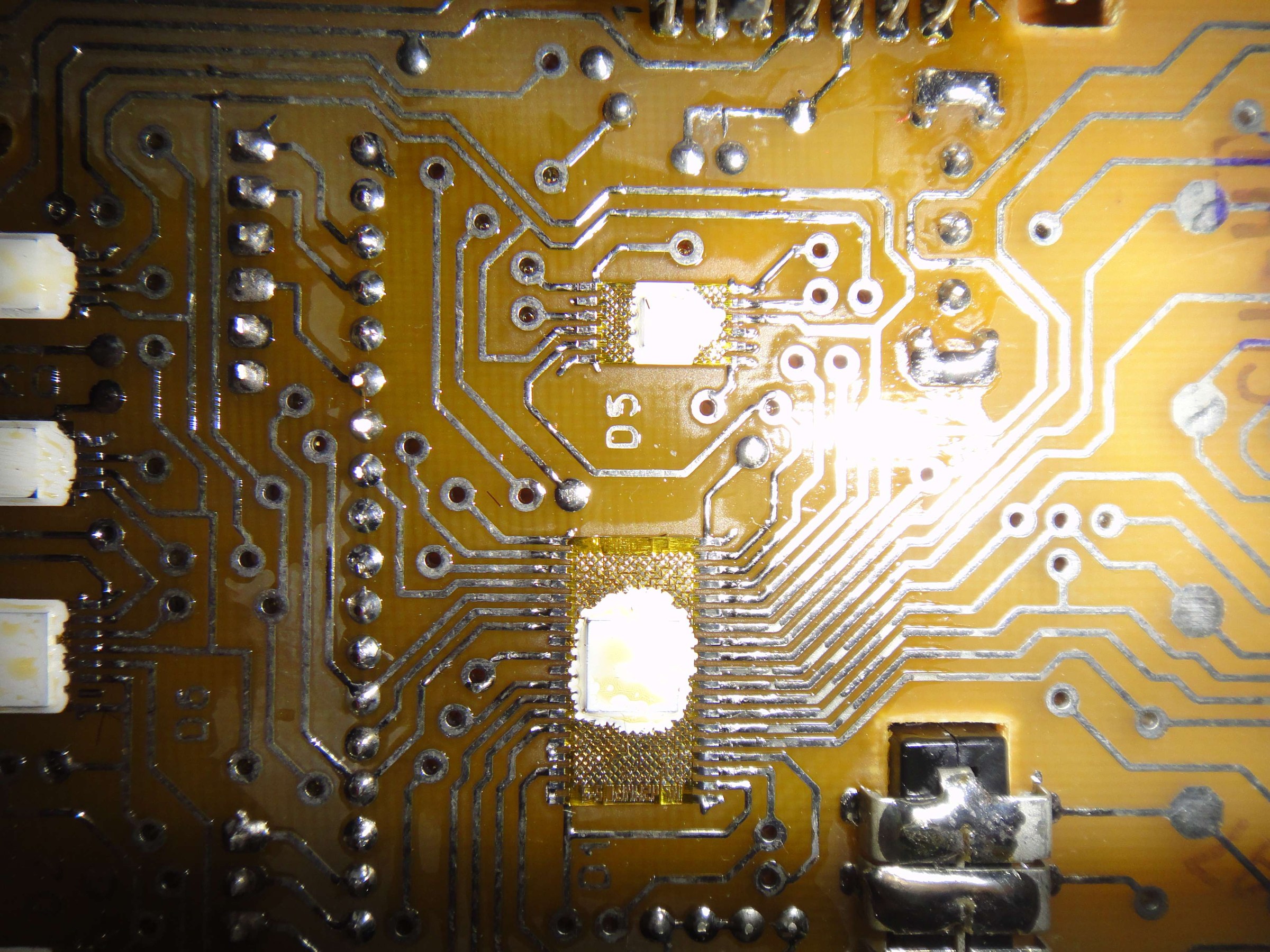
6.1 The chips
The К145 series is a family of p-channel MOS chips for calculators, games and controllers. They run from −15 V or −27 V, and their logic levels are inverted: a high level, near 0 V, is a logical zero, and a low level, −8 to −27 V, is a logical one. The К745 series consists of the same chips without packages, made for mounting directly on calculator boards. The generations:
Table 1 — The К145 series is a family of p-channel MOS chips for calculators, games and controllers. They run from −15 V or −27 V, and their logic levels are inverted: a high level, near 0 V, is a logical zero, and a low level, −8 to −27 V, is a logical one. The К745 series consists of the same chips without packages, made for mounting directly on calculator boards. The generations
| Machines | Chips |
|---|---|
| B3-04, B3-09M, B3-14 (1974–75) | К145ИП1, К145ИП2, К145АР1, К145ПП1; later К145ИК2 |
| B3-18, B3-18A (1975–76) | one К145ИП7 |
| B3-26 family (1977) | К145ИП11 |
| B3-21 (1977) | the К145ИК5 family |
| B3-34, MK-54, MK-56 (1980–) | К145ИК1302, К145ИК1303, two К145ИР2, К165ГФ3 clock |
| MK-61, MK-52 (1983–) | К745ИК1302-2, К745ИК1303-2, К745ИК1306-2, two К745ИР2-2, К745ГФ3-2 clock; the MK-52 adds a К745ИК1801-2 for its EEPROM and modules |
The ИК1302, ИК1303 and ИК1306 are one and the same microcontroller with different contents in their read-only memories. Each has:
- three internal registers, M, R and ST, each 168 bits long, or 42 four-bit digits, and some smaller ones;
- a one-bit adder, which handles numbers as four-bit BCD digits, one bit at a time over four clock ticks;
- and three read-only memories: one of 256 macro-commands, the chip’s instruction set; one of 128 “synchro-programs”, each nine microinstruction addresses long; and one of 68 microinstructions. Sources differ on the microinstruction width, 24, 27 or 28 bits.
Each chip has its own job. The ИК1302 is the dispatcher: it runs the user’s program, reads the keyboard and drives the display. The ИК1303 does the mathematical functions and reads the angle switch. The ИК1306, added in the MK-61, does the degree conversions and logical operations. The ИР2 is a plain dynamic shift register of 1,008 bits.
6.2 One ring
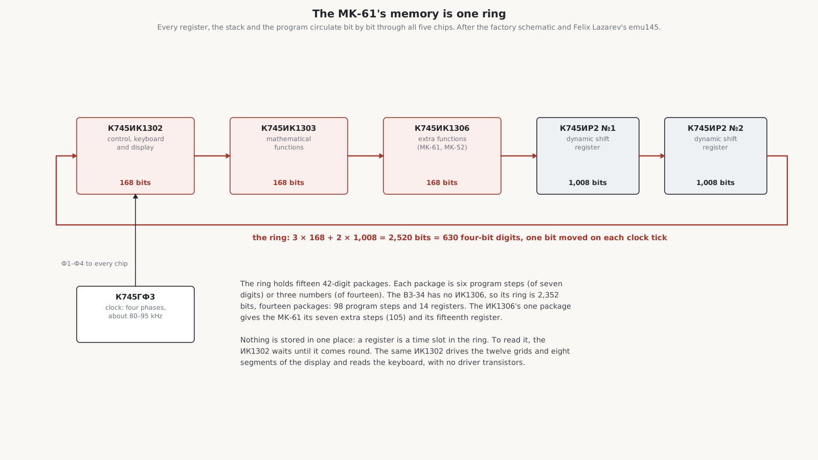
There is no addressable memory anywhere in the calculator. Every chip passes one bit per clock tick to the next through its “register in” and “register out” pins, in a closed loop: ИК1302 → ИК1303 → ИК1306 → ИР2 → ИР2 → back to ИК1302. Everything the calculator knows, the stack, the fifteen registers and the 105-step program, is a pattern of bits travelling round that ring. A register is not a place but a moment: to read one, a chip waits for it to come round.
The arithmetic works out exactly. The B3-34’s ring is 168 + 168 + 1,008 + 1,008 = 2,352 bits, which Frolov gives in just those terms. The MK-61’s adds the ИК1306’s 168 bits, for 2,520 bits, or 630 four-bit digits, which Alexey Sugonyaev describes as fifteen “packages” of 42 digits. A package holds six program steps of seven digits each, or three numbers of fourteen digits. The ИК1306’s one extra package is what gives the MK-61 its seven extra steps (105 against 98) and its fifteenth register. Sugonyaev tried adding a sixteenth package and got seven more steps and another register.
6.3 Ticks, digits and commands
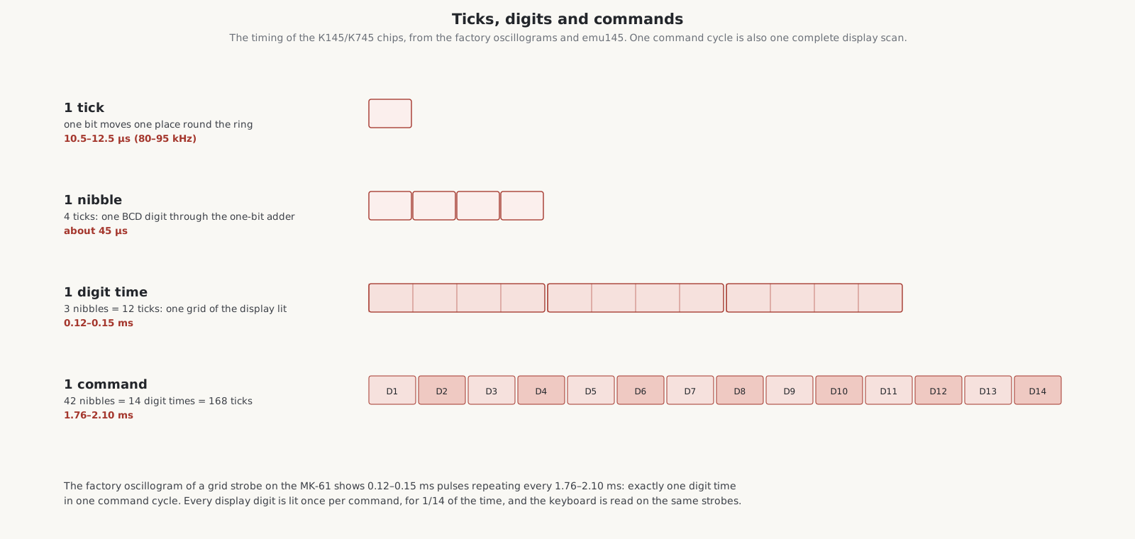
The К745ГФ3 clock chip makes four clock phases, Ф1 to Ф4, which every chip needs: these are dynamic MOS circuits, and the factory pin table calls the phases “pulsed power supply” signals. The oscillograms show phases of 15 V, 2.6 to 3 µs wide, repeating every 10.6 to 12.5 µs: a clock of about 80 to 95 kHz. From there:
- one tick moves one bit one place round the ring;
- four ticks make one digit, one BCD digit through the one-bit adder;
- three digits, twelve ticks, make one digit time, during which one grid of the display is lit;
- fourteen digit times, 42 digits, 168 ticks, make one command cycle: about 1.76 to 2.10 ms.
The factory oscillogram of the grid strobes shows exactly that: pulses 0.12 to 0.15 ms long, repeating every 1.76 to 2.10 ms. Every command cycle is also one complete scan of the display and the keyboard. The manual gives the speed that results: up to 0.5 s for arithmetic, square roots and squares, up to 2 s for logarithms and trigonometric functions, up to 3.5 s for xʸ.
6.4 Thirty keys on two wires
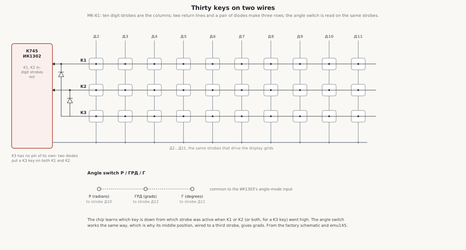
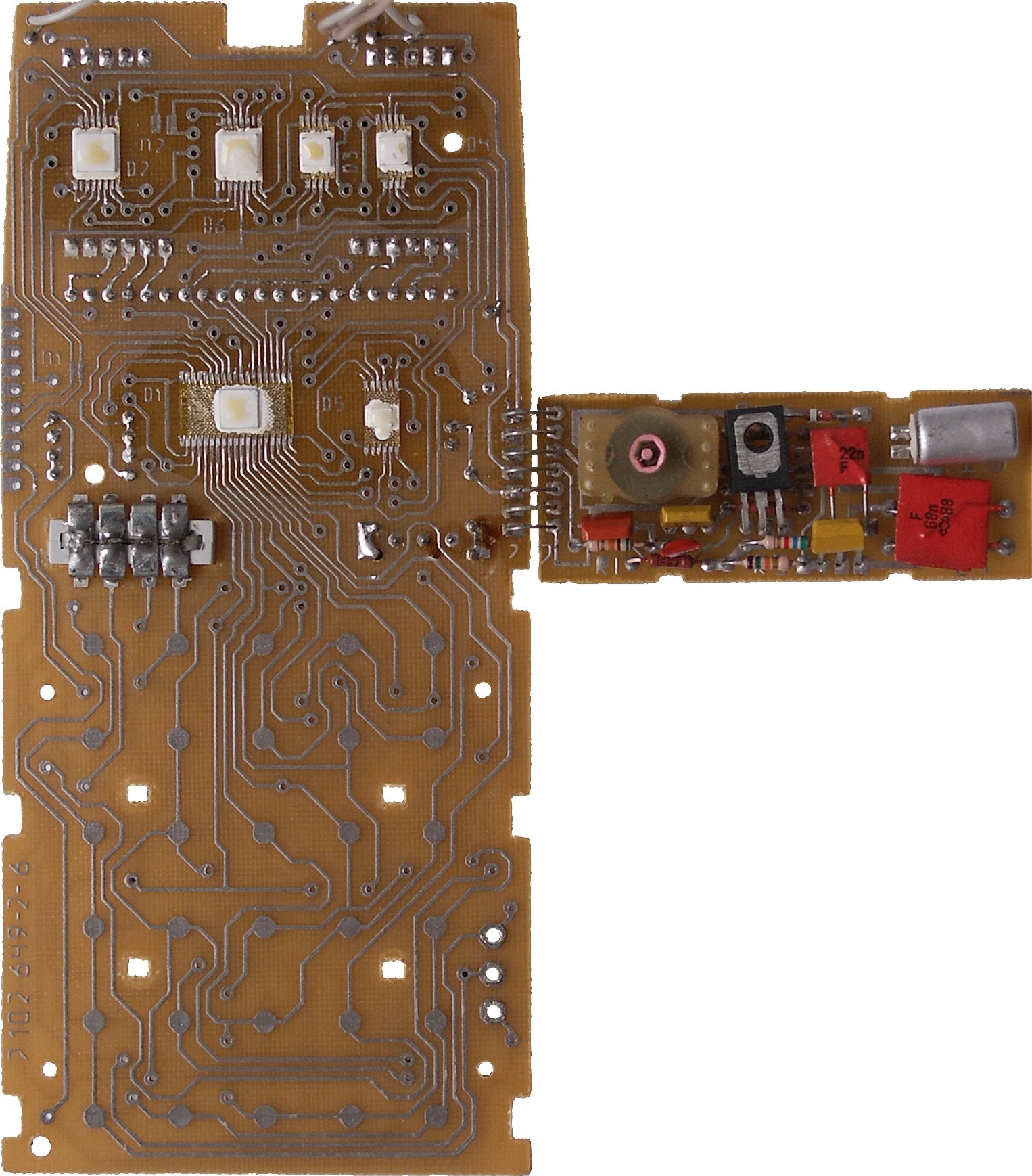
The keyboard is a matrix of three rows and ten columns. The columns are ten of the digit strobes, Д2 to Д11, the same lines that drive the display’s grids. The rows are two return lines, K1 and K2, into the ИК1302. The third row, K3, has no pin of its own: four diodes put a K3 key on both K1 and K2, so the chip reads it as code 3. The keys themselves are bare contact pads on the circuit board, closed by the key above.
The angle switch, marked Р / ГРД / Г for radians, grads and degrees, is read the same way: its three positions connect to three strobes, Д10, Д12 and Д11, and the ИК1303 sees which strobe its angle input follows. That is the hardware reason for something every MK-61 owner discovers: the middle position of the switch, wired to a third strobe, gives grads.
6.5 Fourteen digits to a number
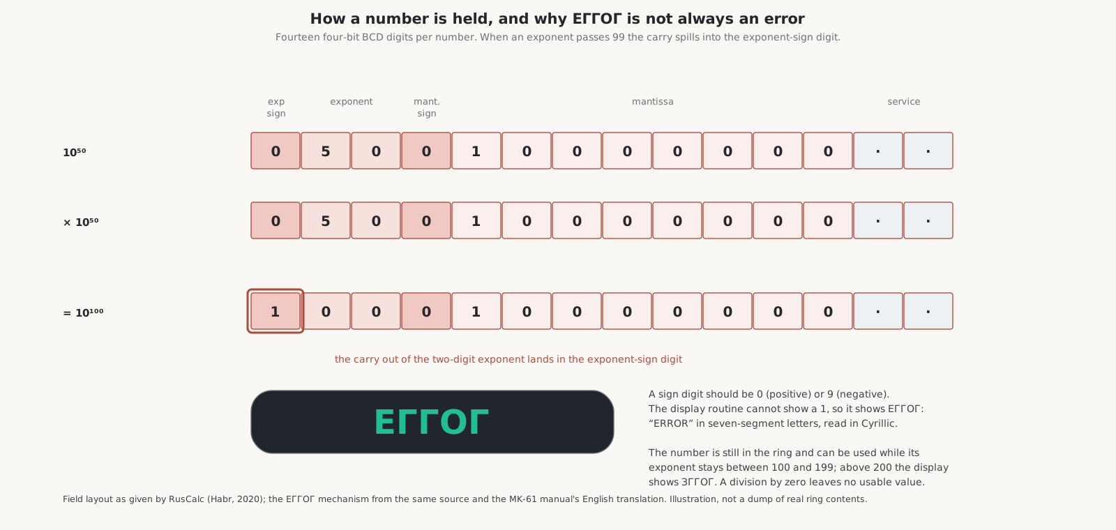
A number occupies fourteen BCD digits: an exponent sign, two exponent digits, a mantissa sign, eight mantissa digits and two service digits. The signs are digits too: 0 for positive, 9 for negative. Because the registers hold four-bit digits, the logical operations of the MK-61 (К∧, К∨, К⊕ and КИНВ) can put the values 10 to 15, the hexadecimal digits, into them, and the display then shows them as odd glyphs that are not figures.
The manual says the display is twelve positions: eight mantissa digits, two exponent digits and two signs, for a range of 1 × 10⁻⁹⁹ to 9.9999999 × 10⁹⁹.
6.6 ЕГГОГ
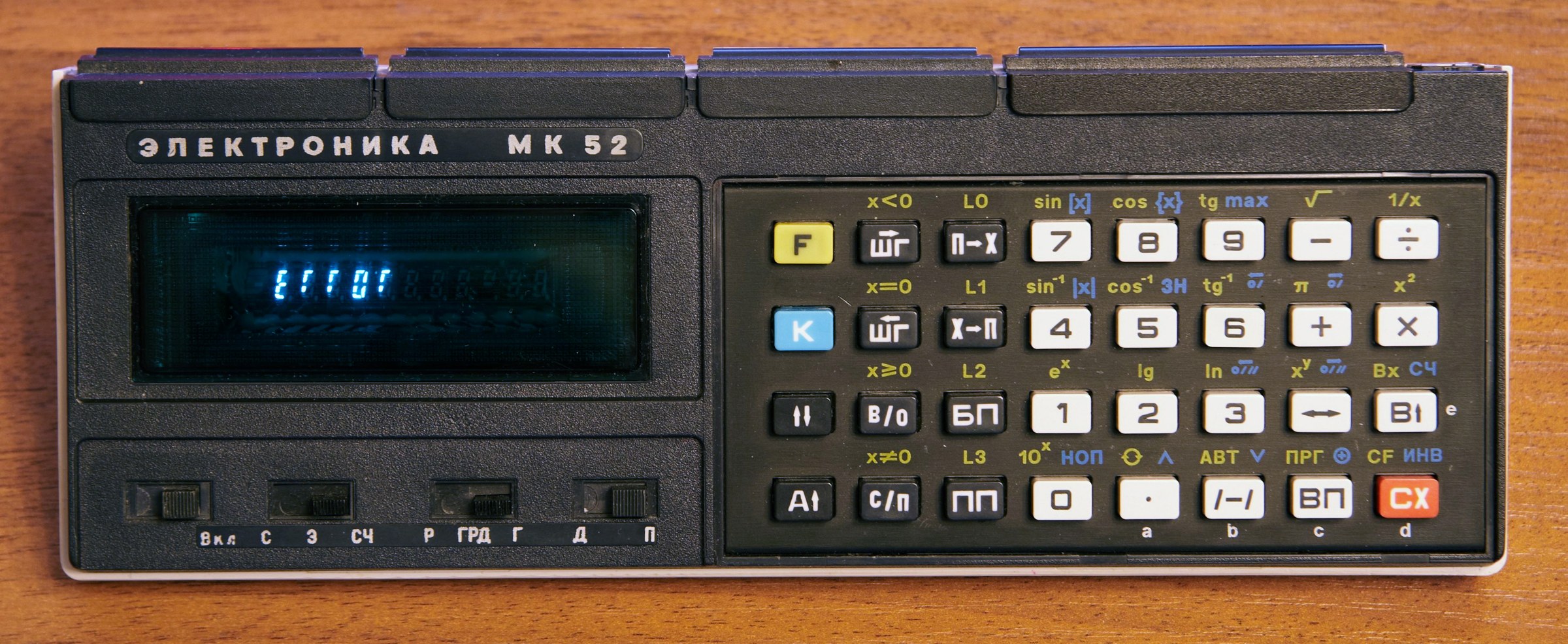
When a calculation goes wrong, the MK-61 shows the word “ERROR” built from seven-segment characters. Russian readers took the seven-segment r for the Cyrillic Г, and read it as ЕГГОГ, a nonsense word that became the name of a whole hobby.
The hardware behind it is the number format above. Multiply 10⁵⁰ by 10⁵⁰ and the exponent becomes 100, which does not fit in two digits; the carry spills into the exponent-sign digit, which now holds a 1. The display routine can show a sign digit of 0 or 9 but nothing else, so it shows ЕГГОГ. But the number is still there, travelling round the ring, and it can go on being used while its exponent stays between 100 and 199. Above 200 the display shows ЗГГОГ. Mesquita’s notes give the test: the command К НОП clears a genuine error but leaves a large number in place. A division by zero, by contrast, leaves no usable value.
The enthusiasts who explored this in the 1980s, in the pages of the magazine Техника — молодёжи, named the territory beyond the normal range in tiers: the ЕГГОГи of 10¹⁰⁰ to 10¹⁹⁹; the ЗГГОГи; “untameable monsters”; “werewolves”; and Тьма, darkness, in which the display goes blank. Exponents wrap round, so that −80 is stored as 920. They called the study еггогология, eggogology. According to Russian Wikipedia, Lazarev’s analysis of the ROMs showed that Тьма is the microprogram caught in an endless loop, and that the ИК1302 produces ЕГГОГ when no other chip takes up a command in time; the article itself flags this as needing a source, so it is best treated as unconfirmed. Ya. K. Trokhimenko’s book of 1990, the main published account of the architecture, says that the handling of errors and non-standard cases in the microcode was simplified, which is where the undocumented features come from.
6.7 Reading the dies
Lazarev’s account, posted on the zx-pk.ru forum through 2011, describes the work. He bought an MK-61, opened it, and found the microcode ROMs readable optically: the diodes that store the bits were visible under a microscope. He photographed each chip twice at different polarising angles; the good images were 700 to 800 MB each, and he vectorised them layer by layer. He began with the ИК1303, whose microinstructions were all known but whose commands and synchro-programs were mostly not; the ИК1302 was mostly known already; the ИК1306 had not been described at all. The emulator was finished and released under the GPL in August 2012, with the raw ROM dumps. Others built on it: Evgeny Troitsky’s ROM reconstruction and simulator, Sergey Vakulenko’s cycle-accurate hardware emulator on a PIC32 microcontroller in 2014, and the Android emulators described in the collecting volume.
The books: Trokhimenko and colleagues, Programmable Microcalculators: Design and Use (1990), and Ochkov and Khmelyuk, From the Microcalculator to the Personal Computer (1990), the key published source on eggogology, both in Russian.
Comments (0)