Soviet Calculators · Volume 5
Inside: Displays and Power
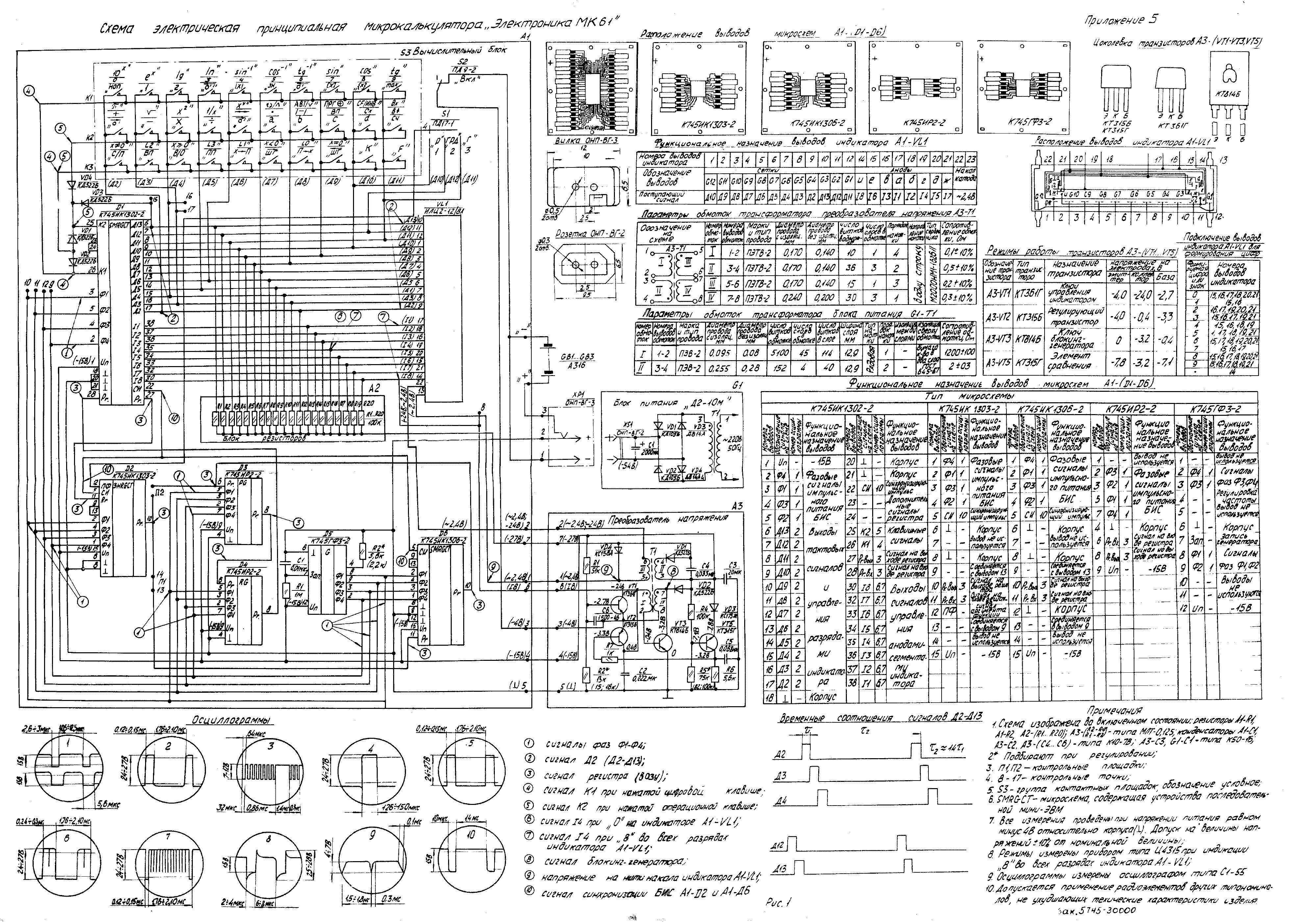
Soviet calculator makers were generous with documentation. The MK-61’s operating manual includes, as its fifth appendix, a full circuit diagram of the calculator on one large sheet: every component with its value, the winding table of the converter transformer, the DC voltages at every transistor, a pin table for every chip, and oscillograms of the important signals. The B3-34’s manual has two such sheets. They make it possible to describe these machines’ power supplies and displays in more detail than almost any Western calculator of the time. This volume uses them, with the display tubes of the earlier machines.
5.1 Nixie tubes in the desk machines
The Soviet Nixie desk machines used Soviet tubes. The attested types are the IN-14 (Iskra 11M, Iskra 111M, Iskra 122), the IN-8-2 (Elektronika 68) and the IN-16 (EDVM). The IN-14 strikes at no more than 170 V and maintains at no more than 150 V, from a supply of at least 200 V. A teardown of an Iskra 111M lists twelve IN-14s and twelve KT605 high-voltage transistors, one per tube, which points to a multiplexed display with a transistor switch on each tube’s anode and a shared set of cathode drivers, the arrangement described in the Nixie series. No factory schematic of a Soviet Nixie calculator has yet been found online.
5.2 Fluorescent tubes
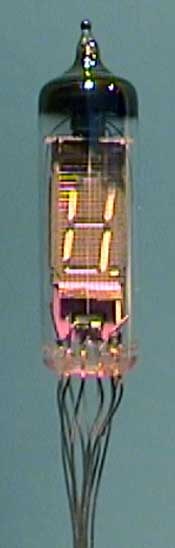
Soviet fluorescent indicators are named by type. ИВ (IV) is a single-digit vacuum indicator, ИВЛ (IVL) and ИЛЦ (ILC) are multi-digit tubes, and the figures after the hyphen appear to give the number of positions and segments: the ИЛЦ2-12/8Л has twelve positions of eight segments (seven and a point), and its final Л marks the green colour.
Table 1 — Fluorescent tubes
| Tube | Used in | Filament | Grid and anode | Other |
|---|---|---|---|---|
| ИЛЦ2-12/8Л (ILC2-12/8L) | MK-61, MK-52, B3-35 | 2.15–2.9 V at 20–24 mA; about 2.4 V AC in the MK-61 | 24–27 V pulses | 12 positions: 8 mantissa digits, 2 exponent digits, 2 signs; digits 2.4 × 4.3 mm; green; 700 cd/m²; life over 10,000 hours |
| ИВЛ2-8/12 (IVL2-8/12) | B3-34 | 2.4 V at 12 mA | 24 V; 0.7 mA anode and 1.0 mA grid per digit | lit one-tenth of the time; 200 cd/m² |
| ИВ-6 (IV-6) | Iskra 122-1, B3-02, Elektronika 155 and many desk machines | 0.85–1.15 V at 50 mA (another source gives 1.2 V) | 25–30 V static, 50–70 V pulsed | single digit, 7 segments and a point, in a 40 × 12 mm bulb |
| ИВ-18 (IV-18) | desk machines; today’s clocks | 5 V at 85 mA by one source | 40–50 V multiplexed, by a forum report | eight digits and a sign position, each with its own grid |
| ИВ-1, ИВ-2 | Elektronika 24-71 | — | — | the first Soviet calculator tubes |
The figures for the MK-61’s tube come from José Mesquita’s notes to his English translation of its manual, and those for the B3-34’s from the table printed on its factory schematic.
5.3 How the MK-61’s display is driven
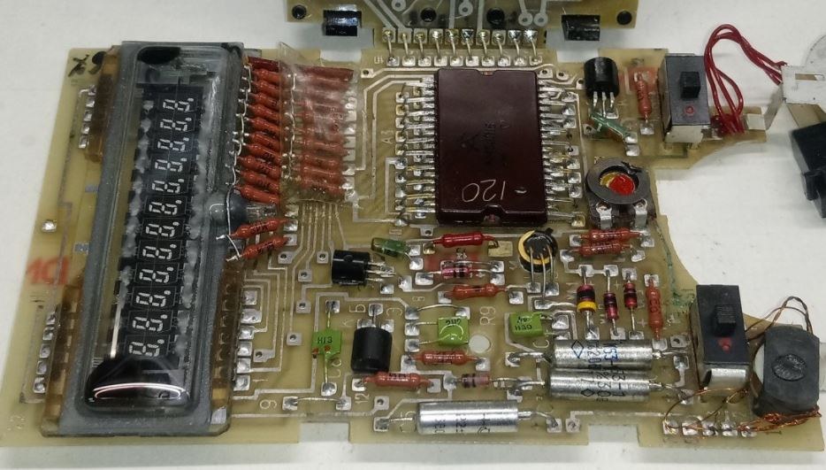
There are no driver transistors. The control chip, the К745ИК1302, drives the tube directly: its pins 6 to 17 are twelve digit strobes, Д13 down to Д2, connected to the tube’s twelve grids, and its pins 30 to 38 are eight segment outputs, И8 down to И1, connected to the tube’s anodes. Twenty 100 kΩ resistors, one on each line, pull every grid and segment down to the −27 V rail; the chip’s p-channel output transistors pull a line up to 0 V when it is to be lit. The tube’s filament, on pins 22 and 23, floats at about −24 V, so that a lit grid or segment is about 24 V above the filament and an unlit one about 3 V below it.
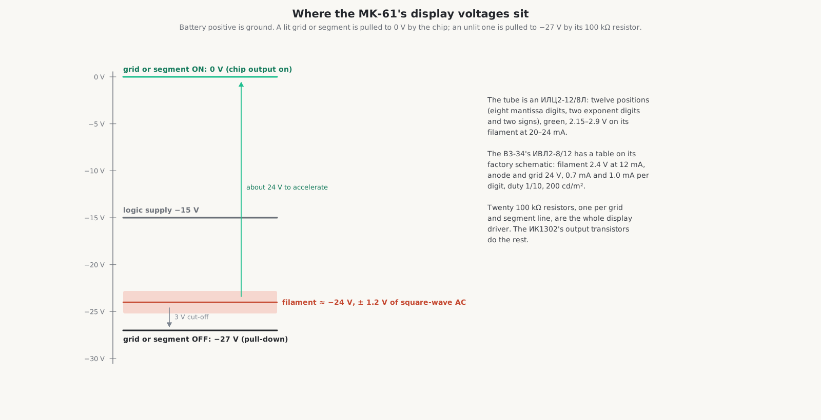
The schematic also gives the tube’s pin map and a table of which pins form each figure: a “0” lights pins 15, 16, 17, 18, 20 and 21; a “1” pins 15 and 16; an “8” pins 15 to 21; the point pin 14. The oscillograms show each grid strobe as a pulse of 24 to 27 V, 0.12 to 0.15 ms long, repeating every 1.76 to 2.10 ms, so every digit is lit for about one-fourteenth of the time. The inside volume shows why the timing is exactly that.
The zener diode VD4 (type КС156А in the MK-61) sets the filament’s offset from the −27 V rail, and with it the cut-off. The B3-34’s schematic carries a note that explains the arrangement: “to cure weak and uneven glow of the IVL2-8/12, the zener VD4 may be fitted in forward polarity”. Fitted the other way round, it drops only about 0.7 V instead of its zener voltage, which lowers the filament’s offset and raises the voltage that accelerates the electrons: a factory-approved brightness boost for an ageing tube.
5.4 The MK-61’s power supply
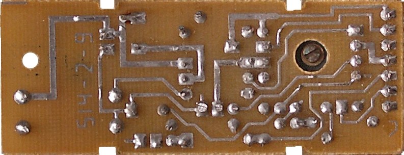
The MK-61 runs on three A-316 cells, the Soviet AA size, giving 4.5 V; alkaline AA cells are fine. The battery’s positive terminal is ground, and every supply in the calculator is negative. A small converter board makes three outputs from the cells: −15 V for the logic, −27 V for the display grids and segments, and about 2.4 V AC for the tube’s filament. The calculator draws about 100 mA with one digit lit and 130 mA with all of them lit, under 0.6 W.
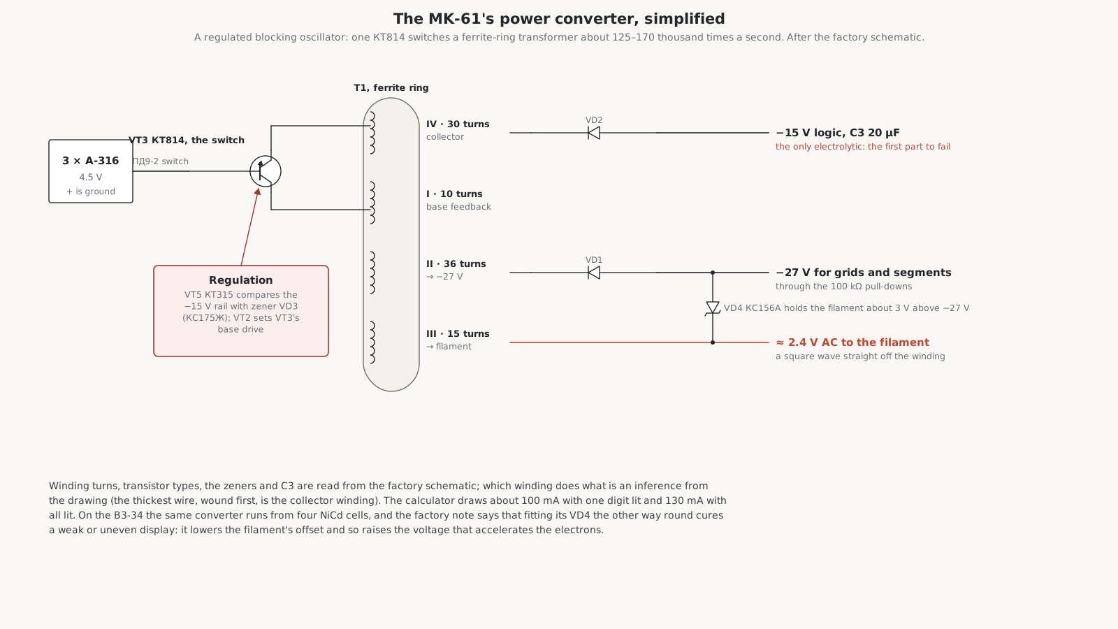
The circuit, from the factory sheet:
- VT3, a КТ814Б, is the switch of a blocking oscillator (“ключ блокинг-генератора”). The oscillograms show it switching every 6 to 8 µs, about 125 to 170 thousand times a second.
- VT5, a КТ315Г, is the “comparison element”: it compares a fraction of the −15 V rail, set by a divider whose upper resistor is chosen at the factory (75, 82 or 100 kΩ), with the zener VD3 (КС175Ж, about 7.5 V). VT2, a КТ315Б described as the “regulating transistor”, then sets the base drive of VT3. The result is a regulated logic supply from a falling battery.
- VT1, a КТ361Г, is labelled the “indicator control switch”.
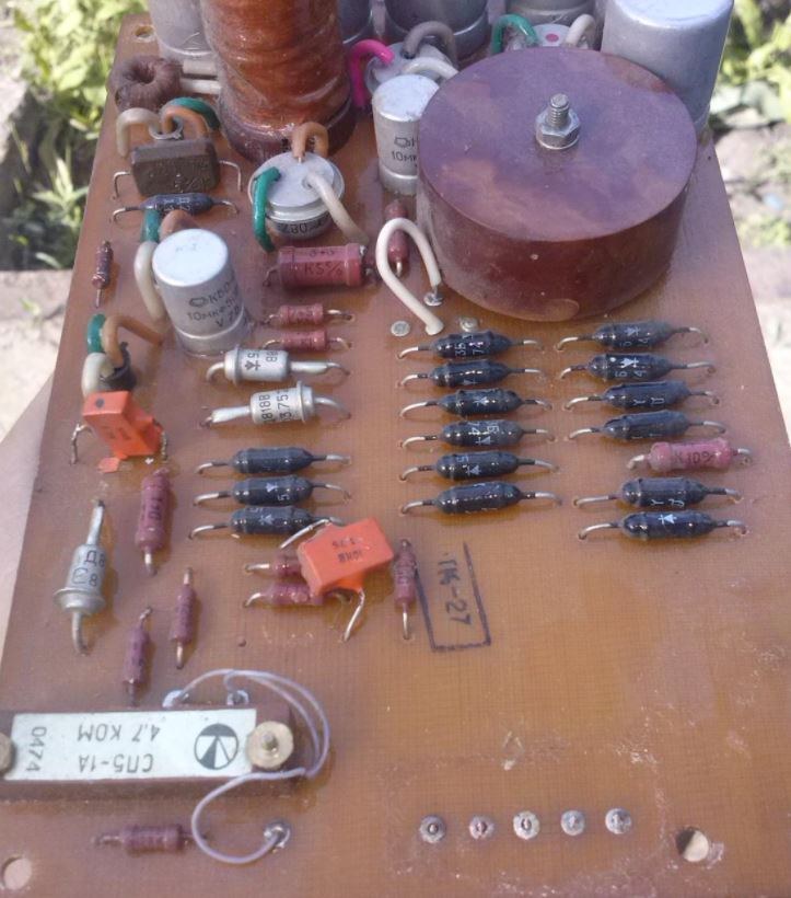
- The transformer T1 is wound on a ferrite ring with four windings: 10, 36, 15 and 30 turns. Which winding does what is not labelled; from the drawing, the 30-turn winding of the thickest wire, wound first, is the collector winding, the 10-turn the base feedback, the 36-turn feeds the −27 V rail and the 15-turn the filament.
- VD1 and VD2, КД522Б silicon diodes, rectify the outputs. C3, a 20 µF К50-16, is the only electrolytic capacitor in the converter, and the one that most often fails.
- The filament supply is a square wave taken straight off its winding, not DC: an AC filament, as the fluorescent-calculator series explains, avoids a gradient of brightness along the tube.
5.5 The Д2-10М mains adapter
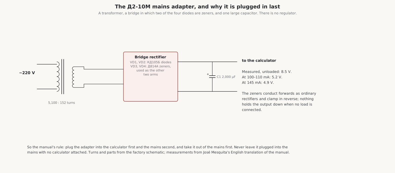
The MK-61 came with an Electronika Д2-10М adapter. Its transformer has 5,100 turns on the primary and 152 on the secondary; its rectifier is a bridge in which two of the four diodes, VD1 and VD2, are КД105Б rectifiers and the other two, VD3 and VD4, are Д814А zener diodes; a 2,000 µF capacitor smooths the output. There is no regulator. Mesquita measured 8.5 V with no load, 5.2 V at 100 to 110 mA and 4.9 V at 145 mA. That is the reason for the manual’s insistence on the order of connection: plug the adapter into the calculator first and then into the mains, take it out of the mains first, and never leave it in the mains with no calculator attached, because the open-circuit voltage stresses the converter.
Other machines had other adapters: the MK-52 a Д2-37А, the MK-85 a Д2-10К, and the B3-34 the БП2-3, which also charged its four Д-0,55С NiCd cells. The B3-34’s converter is almost the MK-61’s design, with windings of 6, 35, 14 and 30 turns and germanium Д9Е rectifiers.
5.6 LED and LCD machines
The early B3-21 of 1977 had red LED digits behind small magnifying lenses; its parts list includes four “АЛС” indicators, and the later version changed to a green fluorescent display. Soviet LED digits of the period include the АЛ304, a gallium-arsenide-phosphide seven-segment digit 3 mm high. The liquid-crystal machines dropped the converter altogether: a directly driven LCD needs only the logic supply. The B3-30 of 1978 used 8 mW, against 600 mW for a fluorescent B3-26; the B3-39 cut consumption to about 1 mW; and the MK-51’s manual gives its power as no more than 0.001 W, from one cell.
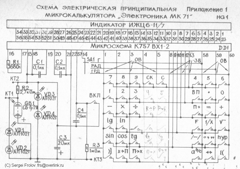
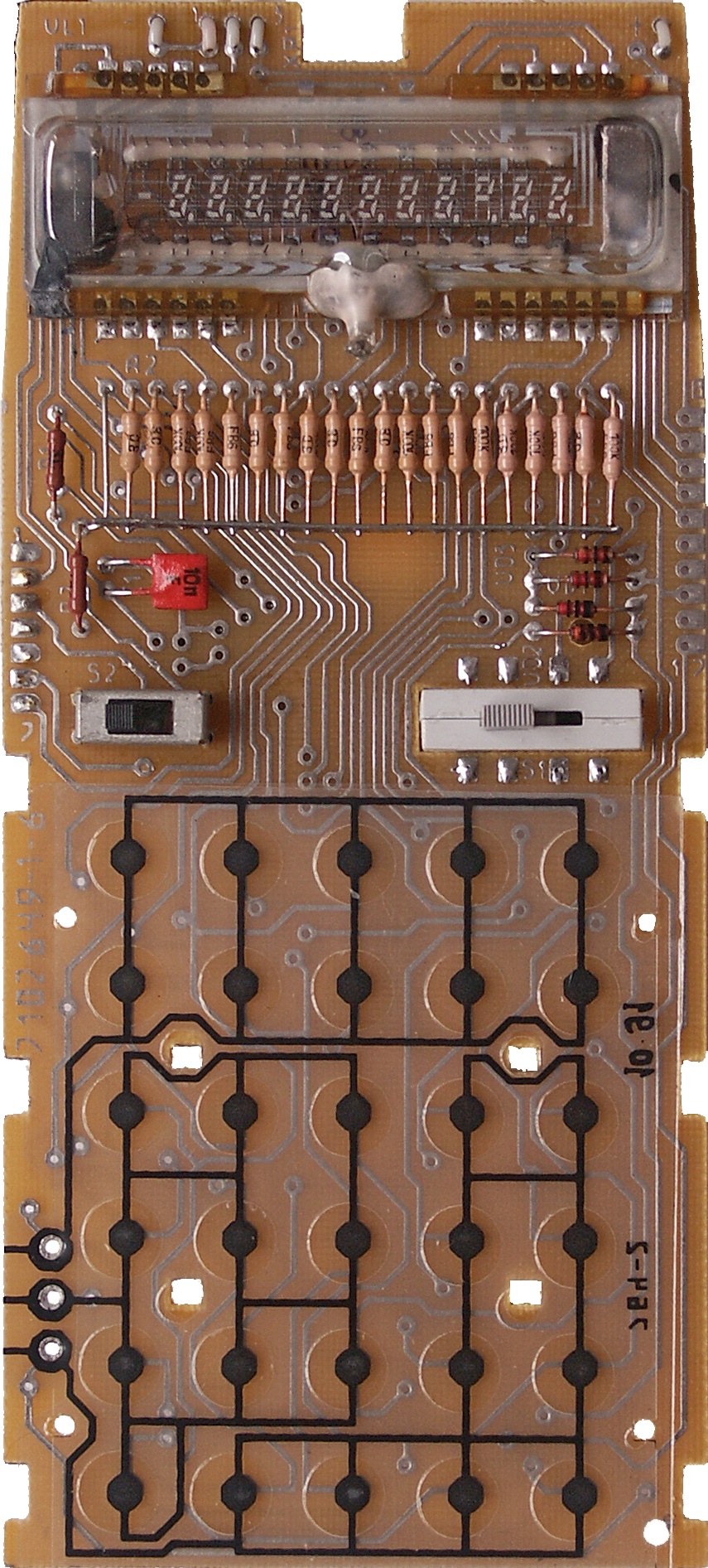
The documents: the MK-61 circuit diagram, the B3-34 factory schematic, the MK-52 schematic with a second sheet marked MEU-4, the schematics of the B3-14, B3-18A, B3-26 and MK-85, the IN-14 and IN-17 reference table and the АЛ304 datasheet.
Comments (0)