Dial Adders · Volume 5
Theory of Operation: How a Lightning Works Inside
From the outside a Lightning looks like seven telephone dials and a row of windows. Inside it is a single gear train about a foot long, made of two interleaved rows of wheels on rivets, a set of sheet-spring pawls and, on the later machines, a toothed clearing bar. It has no springs that store energy and no motion that happens on its own. Every movement in it, every digit entered and every carry rippling up the row, is pushed through the train by the operator’s stylus at the moment of the stroke. That one fact explains most of the machine’s behaviour: why a long carry feels stiff, why the factory said never to oil it, why a single sticky wheel spoils the whole row, and why Hook’s patent was about stopping wheels from spinning too far.
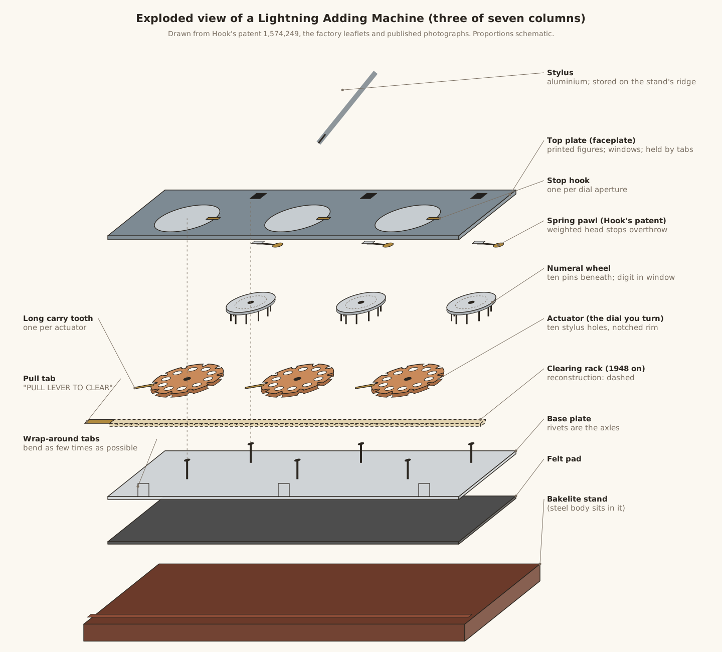
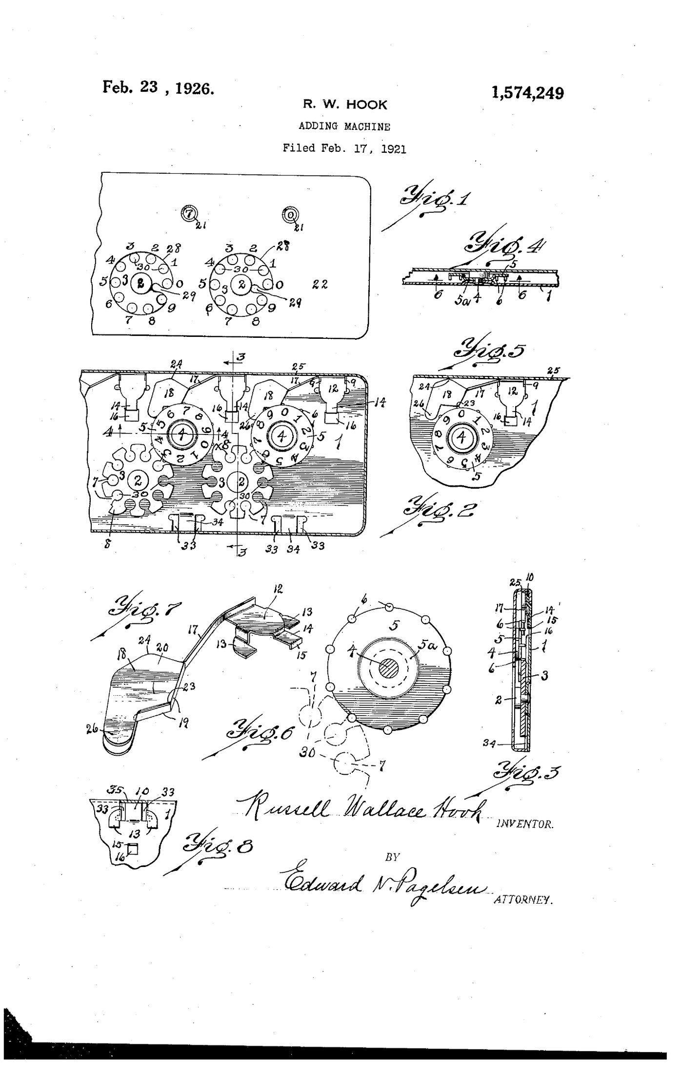
This volume uses the part names and reference numbers of Hook’s patent, US 1,574,249, so that the text, the exploded view and the patent drawing can be read together. The patent describes the Grand Rapids machine of 1921. The Los Angeles machines kept the same gear train and added the clearing lever and, at the end, a carry that works both ways. Where the Los Angeles mechanism has not been documented from the inside, that is said.
5.1 The parts
Working from the bottom of the exploded view upward:
Table 1 — Working from the bottom of the exploded view upward
| Part | Patent no. | What it is | What it does |
|---|---|---|---|
| Bakelite stand | — | moulded tray, about 30° tilt | holds the machine at a reading angle; ridge along the front stores the stylus; Los Angeles only |
| Felt pad | — | felt on the back plate | quiets the machine and stops it sliding on a ledger page |
| Base plate | 1 | flat steel plate, “bumped up” at each rivet | the frame; carries every axle |
| Rivets | 2, 4 | two rows of rivets through the base | the axles: row 2 for the actuators, row 4 for the numeral wheels |
| Clearing rack | — | slotted steel bar with a row of teeth, ending in the pull tab | zeroes every wheel in one pull; post-1948 Los Angeles only |
| Actuators | 3 | one per column: a disc with ten stylus holes (30) and ten rim notches (7) | the dial you turn; drives its own numeral wheel |
| Carry tooth | 8 | one long tooth on each actuator | once per revolution, advances the next wheel to the left |
| Numeral wheels | 5 | one per column, on a raised hub (5a), with ten pins (6) projecting downward and the digits 0–9 printed on the face | the register; shows the digit in its window |
| Spring pawls | 12–26 | sheet-spring clips anchored on tongues (10) of the base, each with a weighted head (26) | a detent that centres each digit in its window and stops wheels from overthrowing |
| Top plate | 22 | printed steel faceplate | carries the figures, the dial apertures (28), the stop tongues (29) and the reading windows (21) |
| Tabs | 33–35 | tabs on the plates’ edges folded round each other | hold the top plate on; there are no rivets on the face |
| Stylus | — | aluminium rod, conical point | the only input |
5.2 The gear train
The heart of the machine is two rows of wheels that alternate along the length of the plate. The actuators are on the lower row. The numeral wheels are on a higher row and in a higher plane, raised on hubs so that their downward-pointing pins hang over the actuators’ rims.
Each numeral wheel sits just to the right of its own actuator, and each actuator, as the patent puts it, “is in constant engagement with the numeral wheel next to the right”: the pins of that wheel ride in the notches of the actuator’s rim, like the pins of a lantern gear. There are ten notches and ten pins, so the gearing is one to one. Turning an actuator one-tenth of a turn turns its numeral wheel one-tenth of a turn, in the opposite direction, and moves the digit in the window on by one.
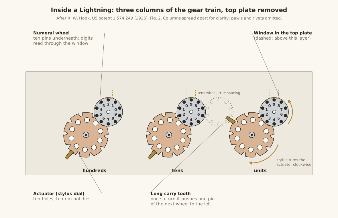
That is why a Lightning’s windows sit above and slightly to the right of their dials, and why the figures around each dial are printed on the faceplate, not on the dial. The dial has no numbers. It is a ring of ten identical holes, and its angular position is the digit. Whatever hole happens to be standing next to the printed 6 is the hole to use for adding 6.
5.2.1 Entering a digit
The stop is a small tongue (29) of the top plate projecting into each dial aperture. On my machines it sits at about four o’clock, in the space between the printed 9 and the printed 0. The figures run anticlockwise from it: 0 just above the stop, then 1, 2, 3 round the top, 9 just below it.
Put the stylus into the hole beside the printed figure n and turn clockwise until it strikes the stop, and the dial has moved exactly n steps. The numeral wheel moves n digits, and n has been added in that column. A hole standing beside 0 is already at the stop and cannot be turned, which is the mechanical form of the leaflet’s instruction that “it is never necessary to register a zero when adding.”
5.2.2 Why the result needs its own wheels
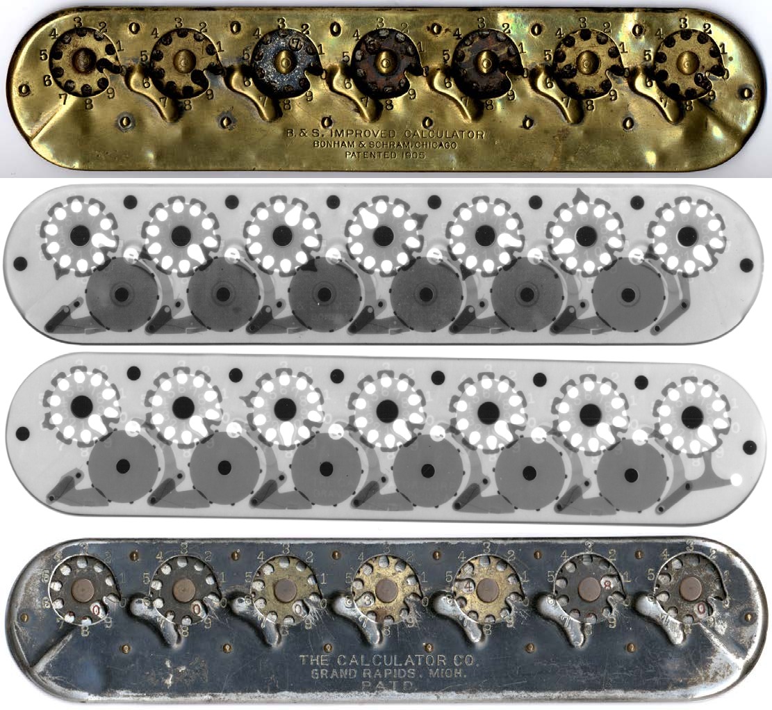
On Bonham’s machine and The Calculator the result was printed on the dials, and because a dial’s holes are all alike, something on the dial had to mark which way round it was. Bonham used one elongated hole, which pushed every dial’s reading to a different position. Hook’s answer was to read the total from the numeral wheels instead, through a straight row of small windows (21) in the top plate. Each numeral wheel is driven by its own actuator and also serves as the receiving gear for the carry from the actuator to its right, so the register wheels and the carry gears are the same parts. As Otnes noticed, the units numeral wheel has no actuator to its right to receive a carry from, and exists purely to show the units digit.
5.3 The tens carry
Every actuator has one tooth (8) longer than the rest. The patent describes it carefully: it is “of such length that it may engage the pins 6 of the numeral wheel next to the left, but the form and position of this tooth is such that it extends inoperatively between the pins 6 of the wheel next to the right.” On its own side the long tooth is just another tooth. On the far side it reaches across to the next column up.
The long tooth is positioned so that it sweeps past the pins of the next wheel to the left exactly once per revolution of its actuator, at the moment the actuator passes from 9 to 0. As it sweeps past, it catches one pin and pushes that numeral wheel on by one pin, one digit. That is the carry: ten steps in one column produce one step in the next.
5.3.1 How a carry ripples
The numeral wheel that receives the carry is permanently meshed with its own actuator. So when the carry tooth pushes the tens numeral wheel one step, the tens actuator turns one step too. If the tens column was standing at 9, that step takes the tens actuator from 9 to 0, and its own long tooth is now at its carry position, pushing the hundreds wheel. And so on up the row.
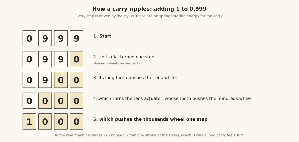
There is no spring anywhere in this chain that stores energy and releases it. The Webb adder had one; the Lightning, like the Calcumeter, does not. Every wheel that moves in a ripple carry is pushed, through the teeth and pins, by the stylus in the operator’s hand, all in the last part of the one stroke. Two practical consequences follow.
- A long carry is stiff. Adding 0.01 to 99,999.99 drags all seven columns at once. Owners report that some dials are “still a struggle because of the many hidden gears”. It is not a fault. It is the machine.
- One stiff wheel stalls everything to its right. If a wheel in the middle of the row is gummed or bent, a carry cannot get past it, and the stylus stroke that needed that carry either stalls short of the stop or slips out of the hole. Carry failure across several places is therefore almost always a single binding wheel. The volume on repair comes back to this.
5.3.2 Capacity and overflow
Seven columns hold 9,999,999, read as $99,999.99. There is no eighth wheel to receive a carry from the leftmost column. Its long tooth sweeps past empty space, so the total silently wraps: 99,999.99 plus 0.01 reads 00,000.00, with no warning.
5.4 The weighted pawl, and why Hook needed it
A stylus stroke ends against a stop, so the actuator being turned cannot overshoot. But a wheel moved by a carry has no stop. It is struck once by a tooth on its neighbour and flicked on by one pin, and if the operator dials briskly it is flicked hard. Without something to catch it, it would coast on past its digit and leave the register wrong. That is “overthrow”, and it is what the Lightning patent is about.
Each numeral wheel has its own pawl, a strip of sheet spring anchored by a clip (12) on a tongue (10) of the base at the back edge of the machine. Its angular middle portion (20) rests between two adjacent pins of the wheel. That is the detent: it pulls the wheel round to the nearest digit position, so that “a numeral of the wheel registers with the reading opening 21”. As a pin passes, it lifts the pawl. If the wheel is moving fast, the pawl is thrown outward, and the patent explains that on earlier machines the pawls were “thrown out so far when the wheels are violently operated” that they could not get back in time to catch the next pin.
Hook’s fix was to add weight. The pawl’s outer end carries a weighted head (26), made of folded plates (18) with a bearing strip (19). Thrown outward, the heavy head lags behind, then “drops in behind the next pin after the one which has raised the pawl and absolutely prevents overthrow”. The side wall of the case (25) limits how far out it can fly. Because the pawl is shaped to ride over the pins in either direction, it “does not prevent reverse movements of the several wheels so that problems in subtraction may be solved.”
The pawl is also what you feel. The faint click as each digit passes, and the way a half-turned dial settles onto a whole digit, are the pawls working. A window showing two half digits is a pawl that is too weak, bent or gummed.
5.5 Clearing
5.5.1 One dial at a time (before 1948)
The Grand Rapids machines and the first Los Angeles machines have no clearing mechanism. Each dial carries a small red mark, a “triangle” on the Los Angeles machines, two red lines on the Grand Rapids ones, beside one of its holes. The leaflet’s instruction is to “place the stylus in the triangle and turn the dial counter-clockwise until it comes to the stop. Repeat this on each dial.”
It works because the triangle marks one particular hole, the one that is at the stop when the column reads zero. Turning that hole anticlockwise to the stop therefore returns the column to zero by the short way back, without ever passing from 0 to 9. So no borrow is generated, and the dials can be cleared in any order. The same mark is the indicator for the early machines’ complement subtraction, described below.
5.5.2 One pull (1948 on)
The redesigned Los Angeles machine has a tab at its left end marked PULL LEVER TO CLEAR. Scherphuis’s photograph of the lever pulled out shows a flat steel bar with a long slot and a row of rack teeth along one edge. The body of the redesigned machine is twice as thick as the early one, room for an extra layer, and the stand gained a cut-out to clear the tab.
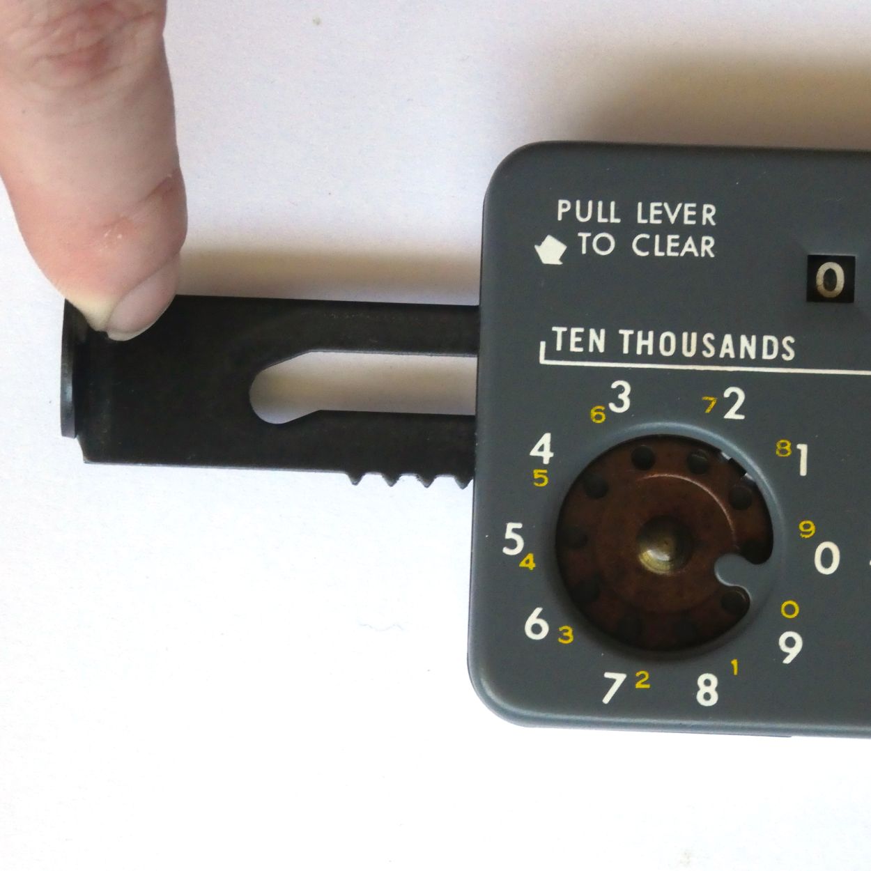
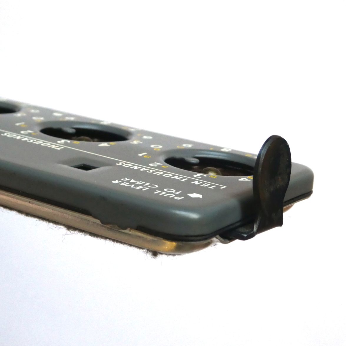
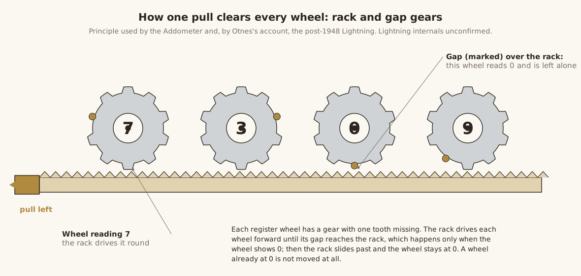
Otnes says the clearing mechanism “is the same as that of the Thomas de Colmar Arithmometer”. The best-documented example of the arrangement in a dial adder is the Addometer, whose clearing Scherphuis describes from the inside. A toothed rack passes each number wheel, and each wheel has a ten-tooth gear with one tooth missing. Pulling the rack drives each wheel round until the missing tooth comes opposite the rack, which is the zero position, after which the rack slides past without touching it. A wheel already at zero is not moved at all. The rack has to travel at least nine teeth’ worth to bring a wheel from 1 all the way round, which is why the lever needs “a firm pull to the left” and, as one owner put it, “takes some effort to pull, especially with all digits in use, and produces a loud click.”
What is not known. No photograph of a Lightning with its top plate off, and no Los Angeles patent, has been found, so the Lightning’s own rack is drawn here by analogy and dashed in the exploded view. In particular it is not documented how the Lightning prevents the wheels being driven through zero during a clear from firing their carry teeth into their neighbours. The Addometer’s alternating four- and five-tooth rack sections and its gear heights are one way of doing it.
5.6 Subtraction
The Lightning subtracts in two different ways, depending on its age.
5.6.1 Direct subtraction (the grey machines)
The last Lightnings are marked TO SUBTRACT DIAL SMALL FIGURES, with an anticlockwise arrow, and their carry works in both directions. Turning a dial anticlockwise takes digits away, and when a column passes backward from 0 to 9 its long tooth catches the next wheel to the left and moves it back by one. That is a borrow, the carry run in reverse. The answer appears in the windows exactly as an addition would.
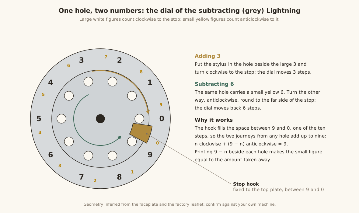
The small yellow figure beside each large white one is that figure’s nine’s complement: 8 beside 1, 7 beside 2, and so on to 0 beside 9. The reason is in the stop. The stop tongue occupies the gap between the 9 and the 0 positions, so it has two faces: the clockwise journey ends on one face at the 0 position, the anticlockwise journey on the other face at the 9 position. From the hole beside large n, the clockwise trip to the stop is n steps. The anticlockwise trip, the long way round to the stop’s other face, is 9 − n steps. Printing 9 − n beside each hole makes the small figure equal to the amount the anticlockwise turn takes away. One set of holes serves both operations, with no extra parts.
A worked example, subtracting 428.87 from 674.30:
Table 2 — A worked example, subtracting 428.87 from 674.30
| Step | Dial | Small figure dialled | Windows |
|---|---|---|---|
| Enter 674.30 by adding | 674.30 | ||
| Hundreds of dollars | 5th dial from the right | 4 | 274.30 |
| Tens of dollars | 4th | 2 | 254.30 |
| Dollars | 3rd | 8 | 246.30 |
| Dimes | 2nd: 3 → 5, borrowing 1 from the dollars | 8 | 245.50 |
| Cents | 1st: 0 → 3, borrowing 1 from the dimes | 7 | 245.43 |
If the result goes below zero, the borrow runs out of the top column and the windows show the ten’s complement of the deficit: 0.00 minus 0.01 reads 99,999.99. There is no sign indicator. An answer full of nines on the left is the machine’s way of saying “negative”.
5.6.2 The triangle method (the early Los Angeles machines)
The add-only machines can subtract too, by complements, and the early Los Angeles leaflet teaches a method that ignores the windows altogether: “The ‘answer’ windows are not used at all in subtraction. Forget them. The red ‘triangle’ on each dial serves as the indicator.”
The triangle on each dial points to a faceplate figure, and that figure is always the nine’s complement of the digit in that column’s window. A dial whose window shows 0 has its triangle at 9, one whose window shows 3 has its triangle at 6. Reading the triangles across the row therefore gives 9,999,999 minus the window total. Adding a number in the windows makes the triangles show the same number subtracted, because the triangle reading is T = 9,999,999 − W, so adding x to W takes x from T. The carries that adding generates in the windows are exactly the borrows the subtraction needs in the triangles.
The leaflet’s own example shows it. Set 674.30 on the triangles (each triangle turned to the figure: “turn the dial so that the ‘triangle’ is opposite the figure 6”, and so on). “The figures in the answer windows will show 325.69 but ignore them”: that is 999.99 − 674.30. Now add 428.87 in the ordinary way. The windows go to 754.56, and the triangles read 999.99 − 754.56 = 245.43, which is the answer. Subtract 86.44 more by adding it, and the triangles read 158.99, as the leaflet says.
The leaflet’s one warning follows from the same arithmetic: “When subtracting from a number having zero, be sure the red triangles are on zero and not on nine.” A cleared dial has its triangle at 9, so when setting up the number to subtract from, every 0 in it has to be set deliberately with its triangle at 0. The leftmost columns are simply ignored. Their triangles stand at 9 and absorb the borrows.
5.7 What the mechanism explains
- “Do not oil.” The pin-and-notch gearing is open, and every tooth is pushed by hand. Oil on it collects lint and grit and, as it ages, gums, adding drag to a train that already has to move up to seven wheels at once. The factory lubricated the axles and said never to add more.
- “Do not use a pencil.” A pencil point is too soft and too blunt. It rides up out of the hole under the side load of a carry, which leaves a short stroke and a wrong digit, and it leaves graphite in the holes and notches.
- “Hold the stylus upright.” The stylus is a lever acting on a hole, and tilting it makes it climb out under load. A long carry is exactly when that happens.
- Errors come from incomplete strokes. Because the stop defines the digit, the machine is only as accurate as the operator’s habit of taking every stroke firmly to the stop.
5.8 Open questions
These are what a careful teardown of a Los Angeles Lightning would answer. Opening one is risky for the reasons given in the repair volume.
- The form of the clearing rack and the gap gears, and how they avoid firing carries during a clear.
- How the carry tooth of the add-only machines passes the next wheel’s pins when a dial is turned backward, and what changed to make it act both ways on the grey machines.
- Whether the green clearing-lever machines can borrow mechanically even though they are not marked for subtraction.
- Whether the pawls on the Los Angeles machines are still Hook’s weighted pattern.
Comments (0)