Giant Curta · Volume 3
The Mechanism at Printed Scale: Tolerances, Materials, and What Breaks
A Curta works because six hundred metal parts hold position to within a fraction of a tenth of a millimetre. Reproducing it in extruded plastic means giving up almost all of that and finding out which of it actually mattered. This volume is the record of that discovery, and it is mostly a list of failures, because the failures are where the information is.
3.1 Establishing the tolerances by experiment
The original drawings specify fits the available processes could not hold, so the first substantive engineering work was not on the machine at all. It was a set of test prints with deliberately varied hole-and-shaft clearances, printed at 0.1 mm layer height for accuracy, and then assessed by hand.
The results, from Wu’s own testing:
Table 1 — The results, from Wu's own testing
| Clearance | Resulting fit |
|---|---|
| 0.35 mm | loose sliding fit |
| 0.30 mm | sliding fit |
| 0.25 mm | transition fit — removable by hand, twistable with effort |
| 0.20 mm | forced fit — removable only with pliers, and damage occurred |
From these he inferred the printer’s accuracy at about ±0.1 mm, or ±0.2 mm once the walls on both sides of a shaft are counted. He then applied standard mechanical fit classes — H7/h6 (LC2), H7/js6 (LT1) and H7/k6 (LT2) — to the model, while noting a result that no metal machinist would accept and every plastic-part builder recognises: any difference in width is worn away in use.
That last observation is the real finding. In metal, a fit class is a specification the part holds for its life. In printed PLA, it is a starting condition that the mechanism itself modifies over the first few hundred cycles. A printed machine breaks itself in.
3.2 The SLS detour
Selective laser sintering was tried first, and rejected for reasons worth recording because they are not the obvious ones.
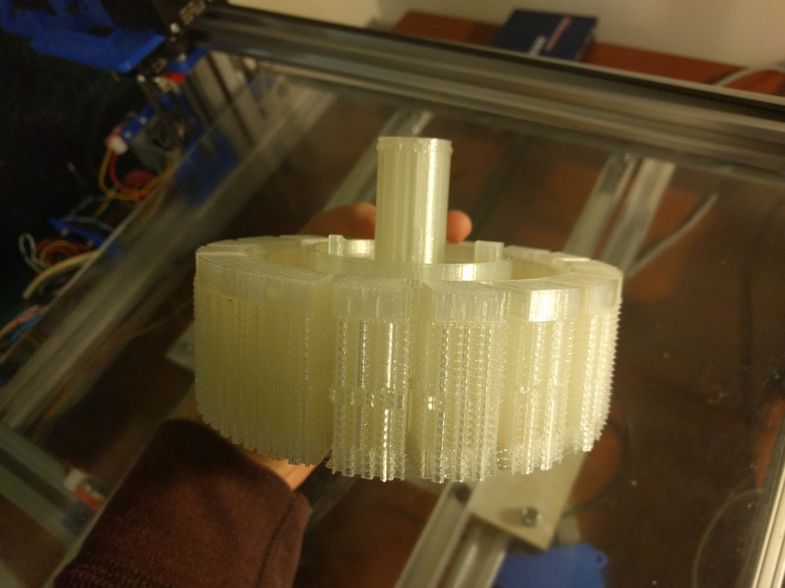
SLS is attractive here because it needs no support material, which matters enormously for a machine full of overhangs and internal features. Wu had test parts — a digit selector axle and its knob — printed by a commercial SLS service. They arrived in good condition and needed only minor cleanup: residual powder on the knob, surface finishing on the axle.
The problems were fit and fragility. The fit was looser than wanted, and two critical features — the fingers that grip the transmission gear, and the top point of the axle — came out too small and too fragile to be useful. Combined with an eleven-day turnaround per iteration, that settled it: the project moved to FDM on his own printer, accepting support material in exchange for same-day iteration.
For a build whose entire method is “print it, try it, find out what is wrong, change it”, turnaround time is a first-class engineering constraint.
3.3 Material and settings
The machine is PLA. The infill strategy is where the engineering is:
- 30% for exterior and low-stress parts;
- 80% for the transmission shafts;
- 100% for anything carrying load — carry pins, carry levers, guide screws, bearing pins;
- 0.1 mm layer height for parts where precision matters.
Simplify3D was used as the slicer, and one of its features shaped the design: the ability to vary print settings at different layer heights, so that infill could be increased exactly where strength was needed rather than across a whole part. Good raft performance also allowed parts to be printed in the orientation the engineering required, rather than the orientation printing preferred — which, as the failures below show, is the single most consequential setting in the build.
One published figure should be treated with caution. Wu’s tolerance article gives primary prints as 0.23 mm layer height at 3000 mm/s. A speed of 3000 mm/s is not achievable on a hobby FDM machine and is almost certainly 3000 mm/min — that is, 50 mm/s, which is entirely ordinary. The figure is reported here as it appears, flagged as very probably a unit slip rather than a claim about the printer.
The printer’s identity is also unresolved. Wu’s own first article describes a large homemade printer with a 16 × 16 × 10 inch build volume; several third-party write-ups say the machine was printed on a gMax 1.5. These are not necessarily in conflict across an eighteen-month build, but no source consulted reconciles them.
3.4 The anisotropy problem, stated by its consequences
The most important single fact about an FDM part is that it is not isotropic. It is strong along a layer and weak between layers, and a part loaded across its layer lines will fail at a fraction of its apparent strength.
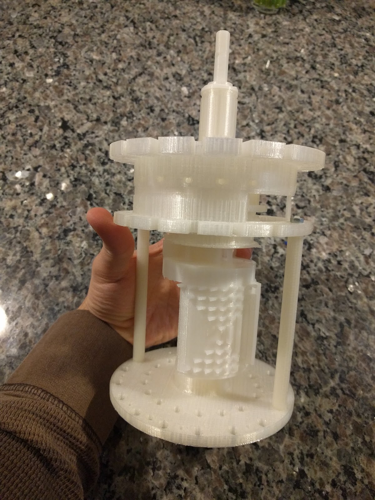
The build produced a textbook demonstration. Printed M5 shoulder bolts sheared apart during threading. Wu’s diagnosis is exact: the layers were aligned normal to the length of the bolt, and the weakest part of a 3D print is between the layers. The fix was not a stronger material but a different orientation — printing the body support columns horizontally, with raft and brim to hold them down.
This is the mechanism-level cost of scaling up. A Curta’s real shoulder bolts are steel and their internal grain is irrelevant. Their printed equivalents have a grain direction that must be designed for.
3.5 The springs
Springs cannot be printed, so they were made.
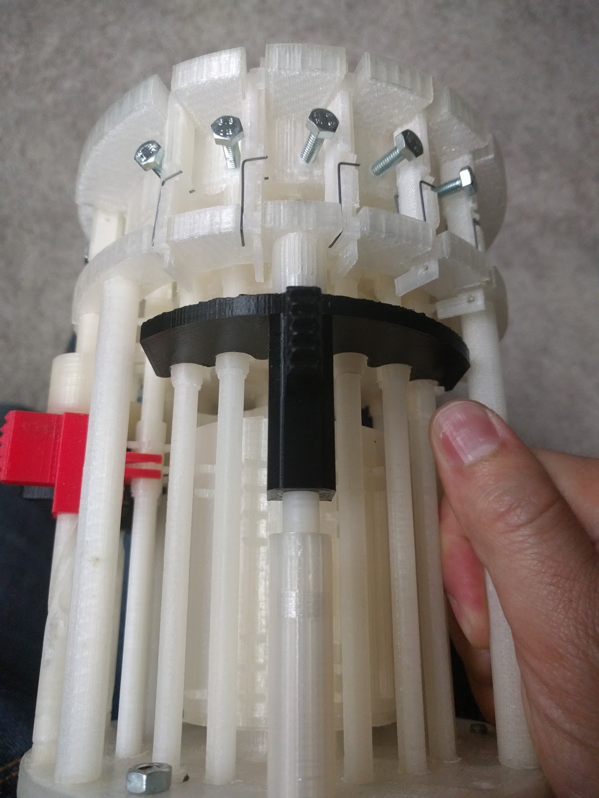
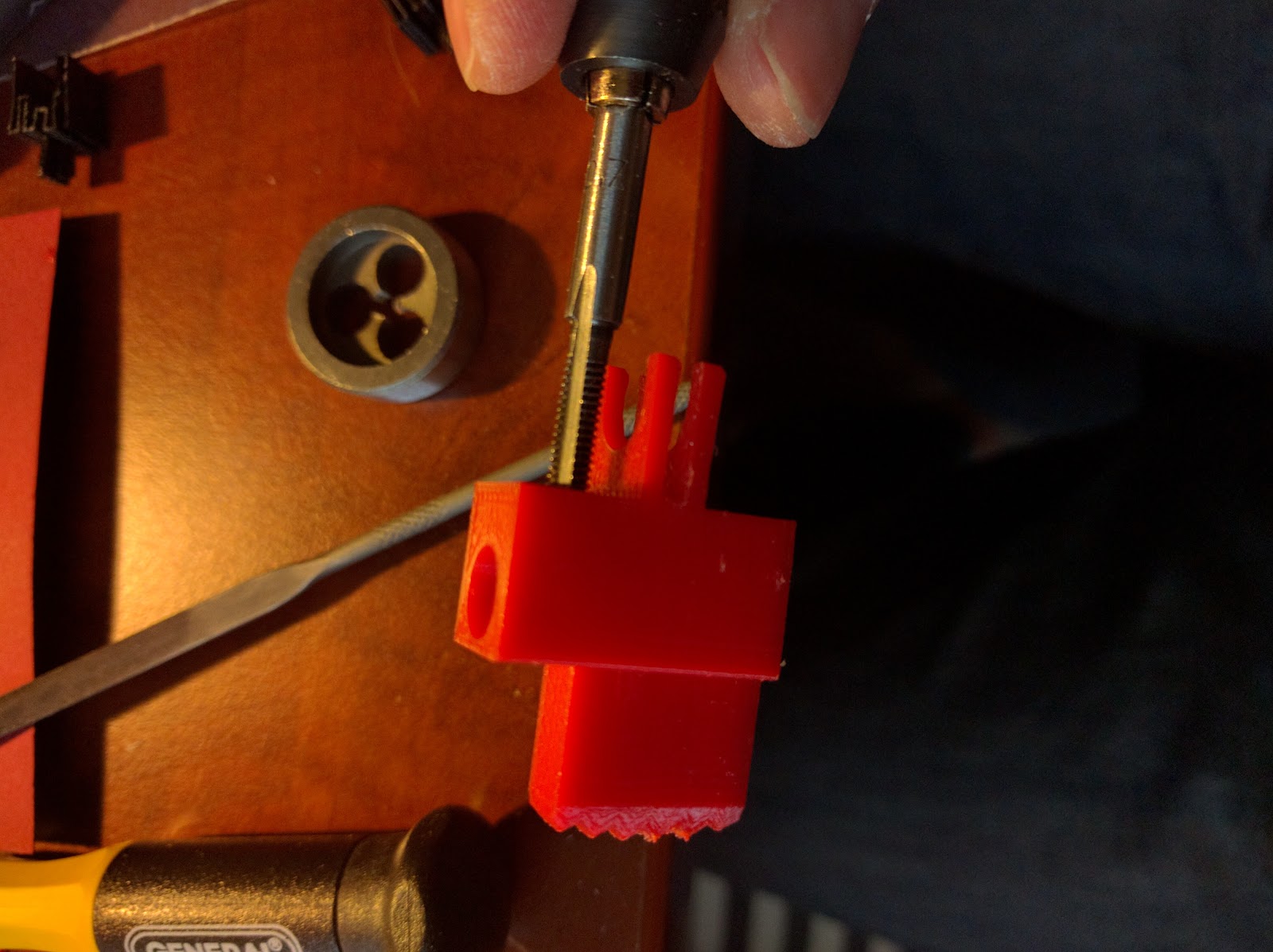
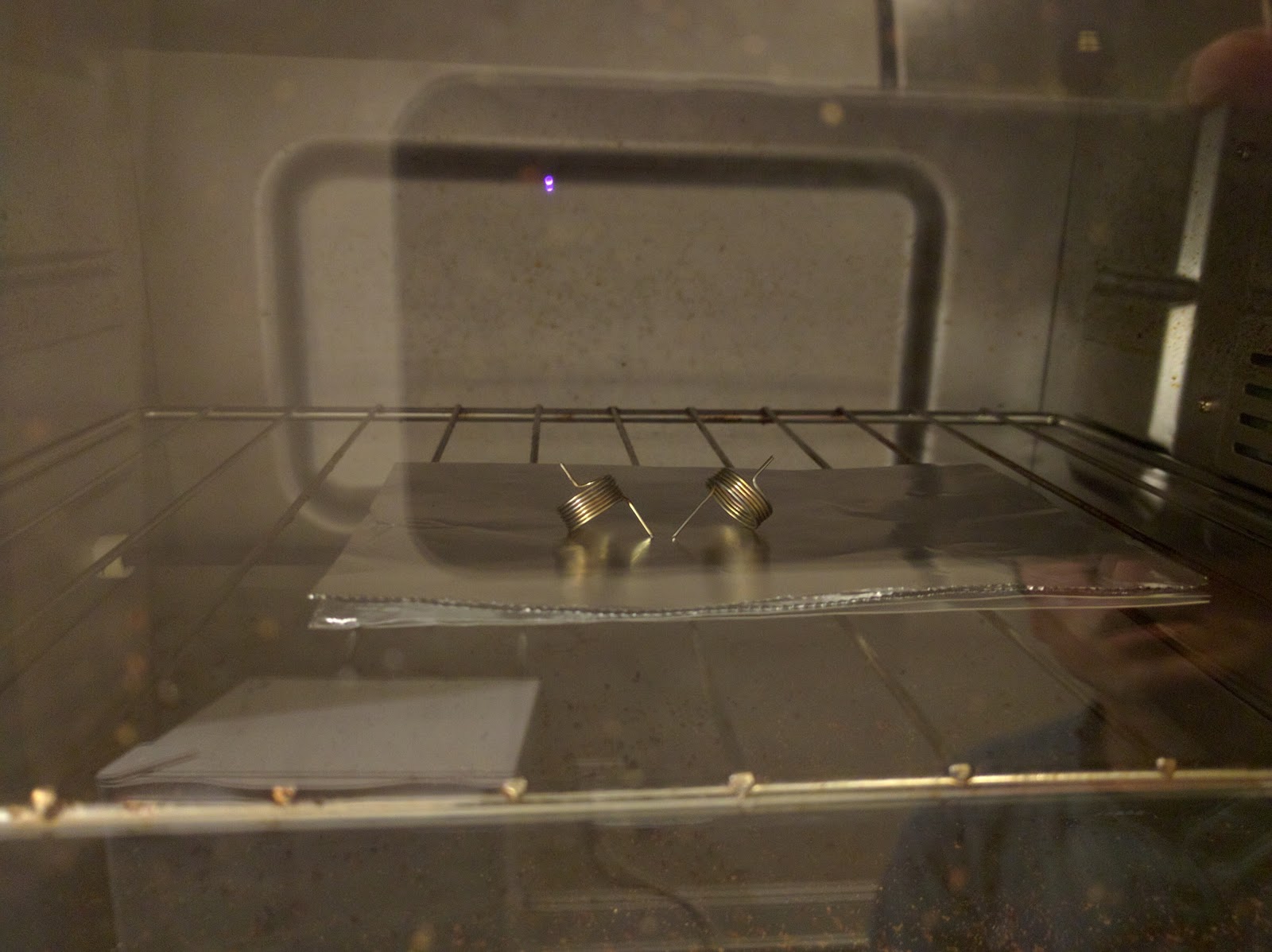
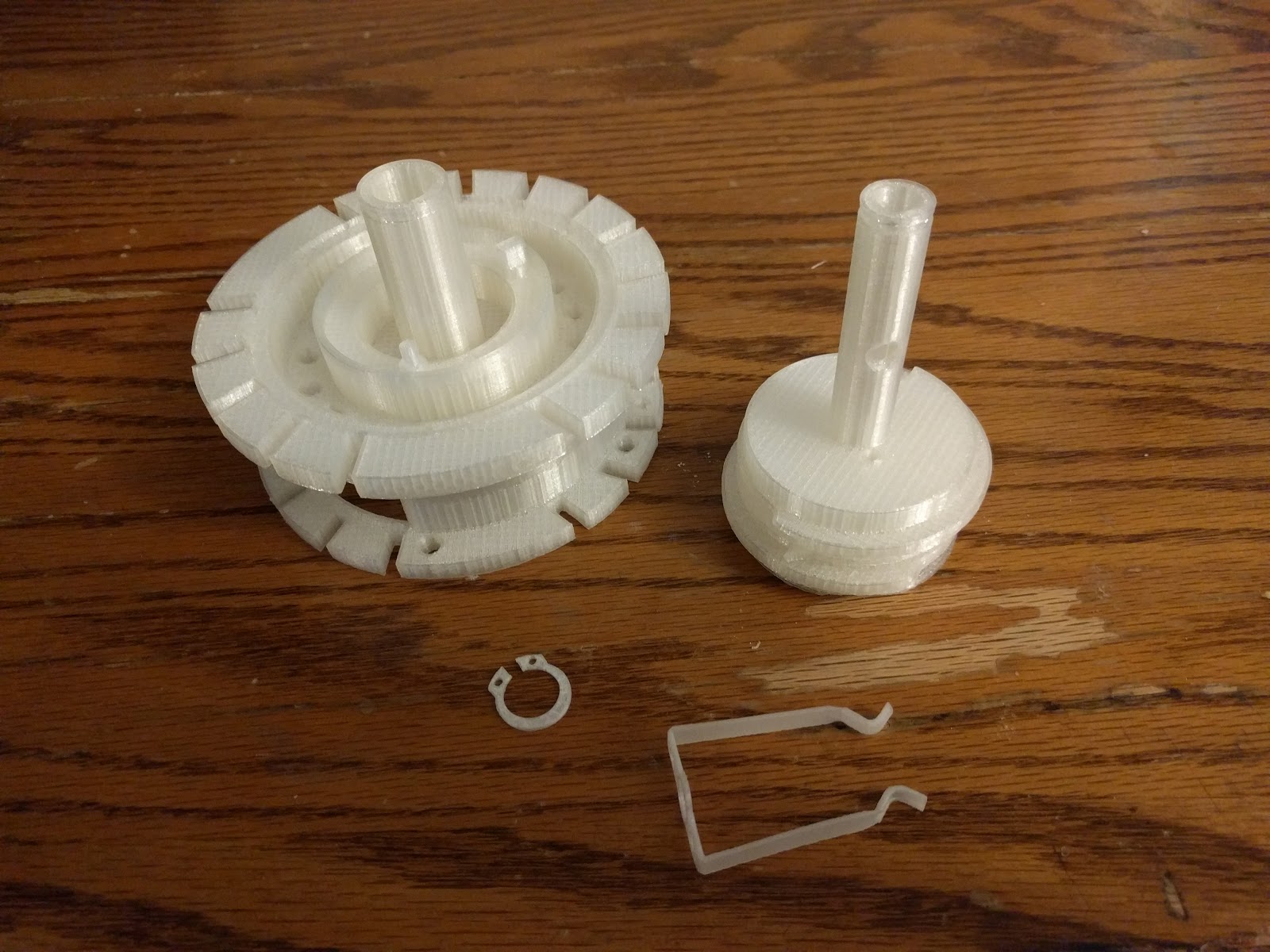
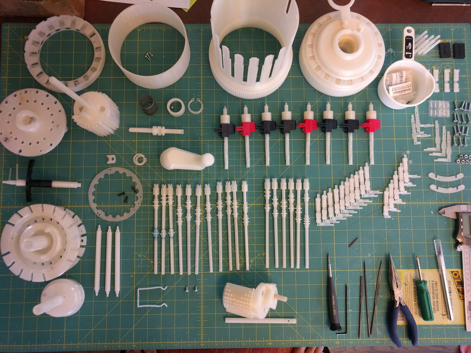
Music wire was wound on drill-mounted mandrels using a purpose-printed jig, with tension maintained by pliers while the drill turned slowly. The carry lever springs are 0.6 mm music wire. Commercial springs from McMaster-Carr were used where a standard part would serve. The wound springs were then tempered in a kitchen toaster oven at 450–500 °F for thirty minutes.
There is a safety note in the record that deserves repeating rather than paraphrasing away: one spring unwound during winding and the whipping wire left a nasty bruise. Wire under tension on a rotating mandrel is genuinely dangerous, and the injury here was to an experienced builder being careful.
3.6 The ball bearings, and the best piece of sourcing in the build
The Curta uses small steel balls as detents and bearings. At 3:1 these need to be larger than the original’s, and precision balls in odd sizes are an expensive specialty item.
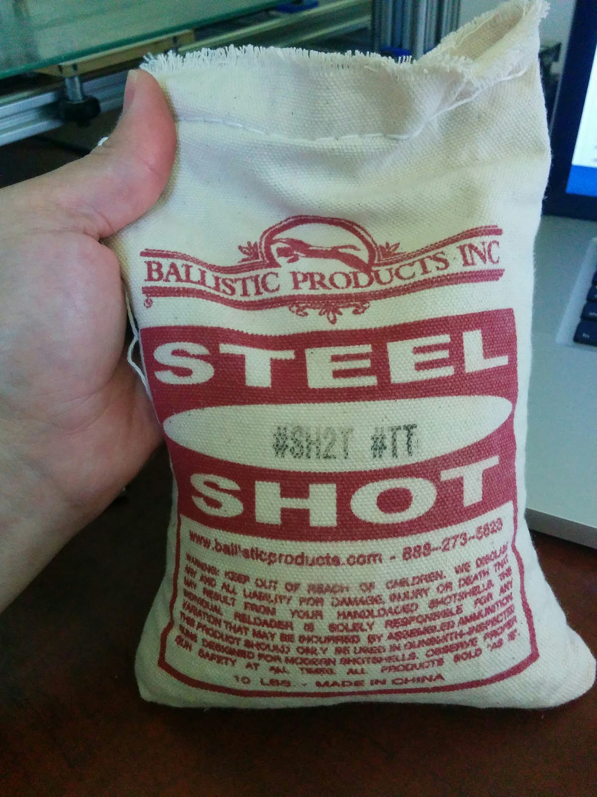
The solution was a ten-pound bag of TT-size steel shot from a shotgun-reloading supplier. Shot is manufactured in graded sizes to a consistent diameter, is hard, and costs a few dollars a pound. It is one of those substitutions that is obvious only afterwards.
3.7 What broke
The failure list, assembled from the build articles, is the most useful thing in this dive for anyone attempting something similar.
The step drum, printed with its teeth twenty degrees out of position. A modelling error, caught only after printing. Thirteen hours per reprint.
The main axle, ninety degrees out of orientation, traced to inconsistent or incorrect original engineering drawings and fixed by changing the key orientation.
Printed M5 shoulder bolts, sheared during threading through layer-plane failure, as described above.
The main shaft, fractured at the crank handle pin hole. The cause was not really the print: gears were not spinning freely within the reversing lever engagement, creating friction that seized the mechanism, and force was applied instead of the binding being diagnosed. Wu’s own account of the lesson is unsparing — he applied force rather than methodically finding where it was binding. The replacement was printed at 100% infill rather than 30%.
The main shaft pin, which fractured twice in later use and was repaired with epoxy reinforcement.
Crown gear tops on the transmission shafts, described as fragile and needing reprints after breakage.
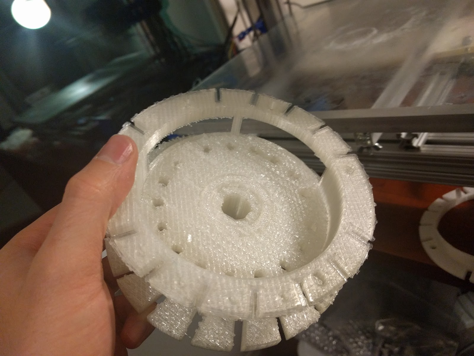
The bottom ring of the tens bell, warped during printing; the model was altered to align the rings properly and to increase the footprint in contact with the bed.
The main body, which curled off the bed during cooling on a printer without a heated bed, forcing the print to be cancelled.
Clear PLA from one supplier, which printed well but adhered to its supports so tenaciously that removal damaged parts.
The carriage casting, which caused a two-month debugging period and was resolved only by reprinting it in the opposite orientation — the anisotropy lesson arriving a second time, in a part where it was not expected.

3.8 Assembly, friction, and the carry
Assembly at this scale is an exercise in friction management rather than fitting.
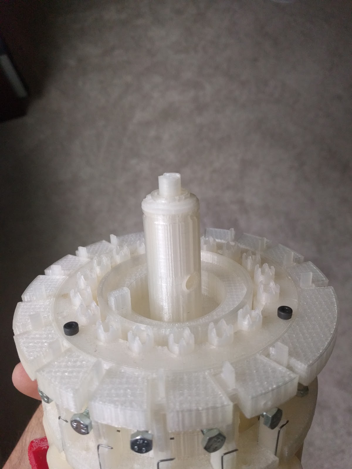
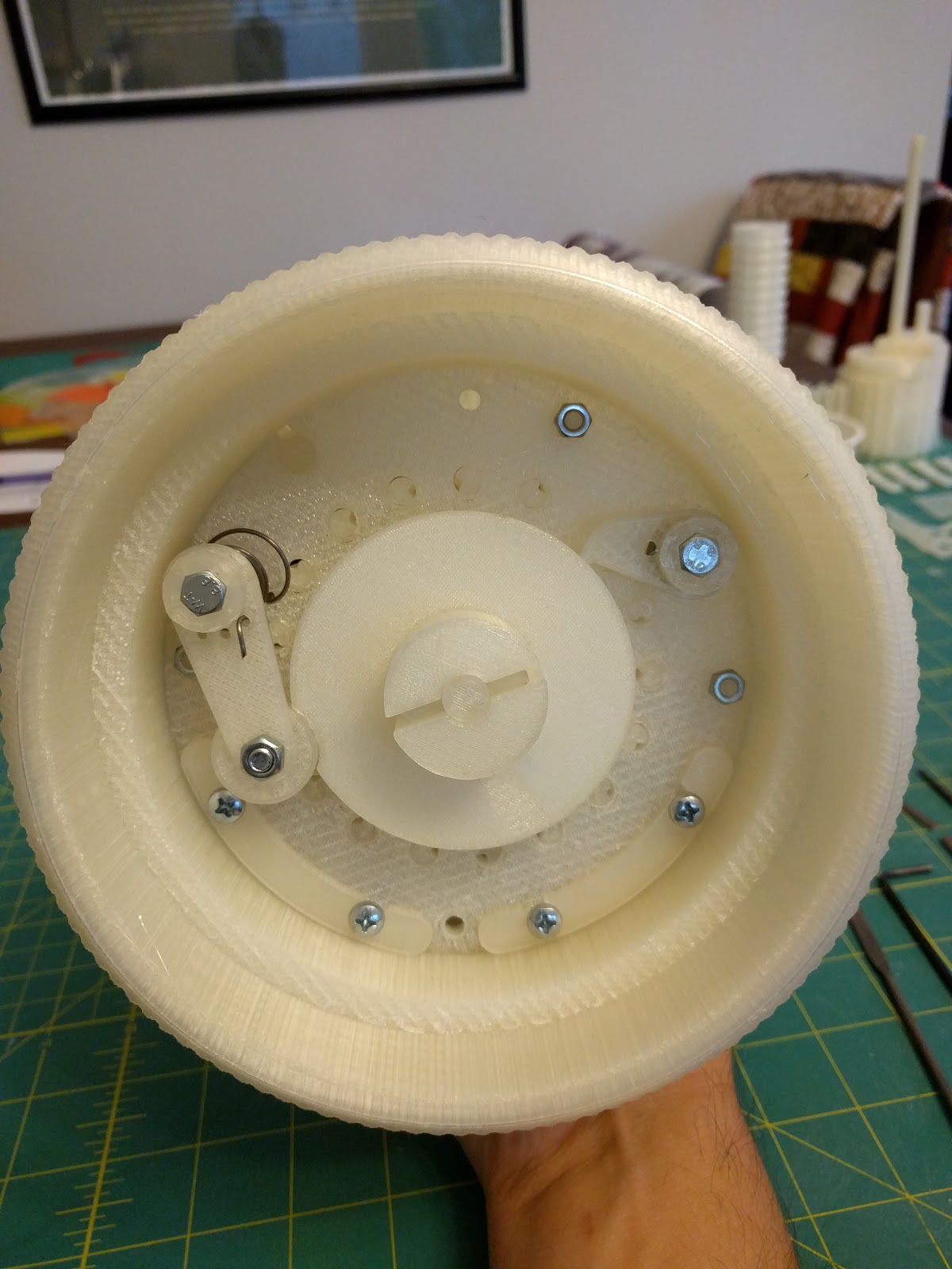
The tens carry required each of the roughly fifteen carry levers to be calibrated individually, adjusting its height so that it aligned correctly with the ramped reset section of the tens bell. Wu describes this as taking time and patience, with multiple height adjustments per lever. In the original, that alignment is held by manufacturing precision; in the printed machine it is set by hand, lever by lever.
Squeaking and binding in the transmission were resolved with PTFE dry lubricant, after which the transmission ran smoothly. Even so, the first full assembly hung up repeatedly and had to be completely disassembled so that every joint could be friction-tested individually before reassembly — which is the discipline the broken main shaft had taught.
3.9 What works, and what does not
Wu’s own summary is the honest one: the Curta now functions well.
Working: addition; subtraction; multiplication by lifting and rotating the carriage; and the tens carry. Subtraction is reported as working beautifully, but with more friction than addition — which makes mechanical sense, since the complement row engages more teeth.
Not fully working: the clearing ring is tough to turn and does not always leave every digit on zero. That is precisely the fault the Curta collecting literature identifies as the most common real defect in original machines too, which is a quietly satisfying convergence: the hardest sub-mechanism to get right is the same one in metal and in plastic.
And an honest limitation on verification. At the point of the write-up, the result dials did not yet carry printed numbers, so — in Wu’s words — he had not been able to do much actual maths. The mechanism demonstrably operates. A full arithmetic verification against worked examples is a separate claim, and the record consulted does not support asserting it.
Comments (0)