Giant Curta · Volume 2
From 145 Engineering Drawings to 116 CAD Models
The Curta was designed on paper, twice, by a trained toolmaker. Reproducing it as a printable object meant translating that paper into solid models — and then deciding, part by part, which of Contina’s decisions were about the mechanism and which were about how metal is made. Only the first kind had to be preserved.
2.1 The starting material
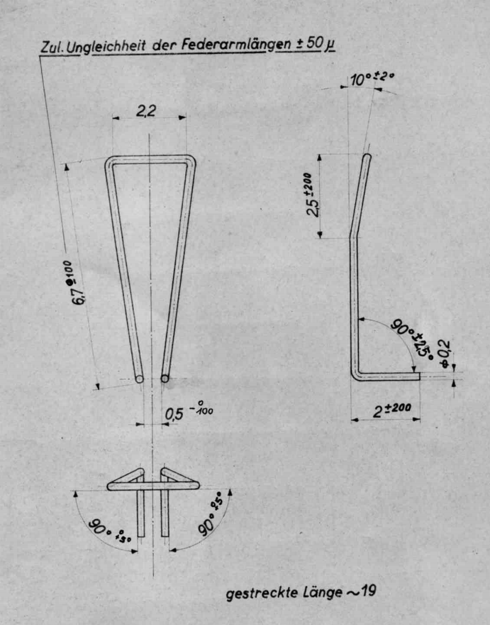
Wu worked from the original Curta engineering drawings, which survive and circulate among collectors and researchers. His account puts the drawing set at 145 sheets and the original machine at roughly 605 total parts, of which around 150 are unique — the rest being repeats, principally the per-digit-column components that appear eight times over in a Type I.
That unique-part figure is the one that makes the project tractable. A machine of six hundred parts sounds impossible to model; a machine of a hundred and fifty distinct parts, most of them small turned or stamped pieces, is a long job rather than an impossible one.
The 145 drawings became 116 CAD models. The reduction is the interesting number, and it is entirely deliberate.
2.2 The CAD
Wu used Onshape, on its free public plan, and taught himself the software from the vendor’s own video library, having no prior mechanical-engineering background. He has noted liking that he could model on a phone or on any computer, which for a project worked in eighteen months of evenings is not a trivial consideration.
The choice has a consequence worth naming: a free Onshape public document is public. The models, and the design history behind them, were visible throughout — which is part of why the project was noticed while it was still unfinished, and why the released files could be picked up by others. The count of over 28,000 downloads reported for the published model is downstream of that decision.
2.3 What was consolidated, and the rule behind it
The reduction from 145 drawings to 116 models came from combining parts that exist separately in the original only because of how they were manufactured.
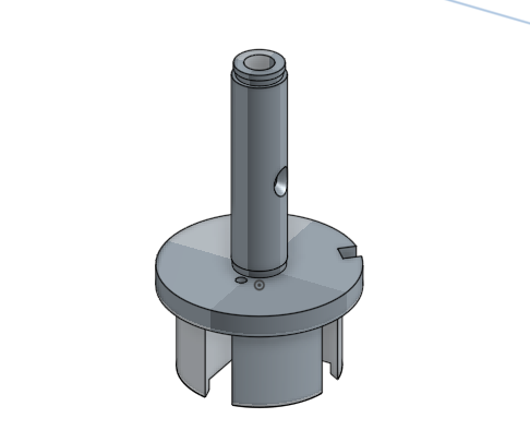
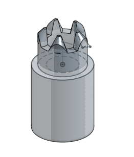
A metal machine shop makes a gear and a sleeve separately and presses them together, because that is how a gear and a sleeve get made. A printer produces arbitrary solid geometry in one operation, so the assembly has no reason to exist. The gears and sleeves that the stepped drum turns were therefore combined into single printed parts. The tens bell and the step drum, both multi-segment assemblies in the original, became monolithic prints.
The rule Wu applied, stated in his own terms, was to combine parts that did not need to be separate — with the practical addition, in later articles, that consolidation also avoids press-fitting fragile printed components, an operation that breaks printed parts far more readily than metal ones.
Not everything could be consolidated, and two categories resisted.
Threads. Two parts in the original require M50 threads. Cutting threads at that diameter was cost-prohibitive, and printing usable threads at that size is not reliable, so the parts were redesigned either to snap together in a keyed way or to be drilled and pinned.
Fasteners. Standard metric screws were bought online. Non-standard screws specific to the Curta had to be either designed into the parts they fastened or threaded by hand with taps and dies.
2.4 The parts that cannot be printed at all
Springs are the hard boundary of the whole project, and they are why a printed Curta is not purely a printed object.
The Curta uses several non-standard springs, including torsion springs and the distinctive “spider spring”. A printed spring is not a spring: Wu’s attempt at one for the tens bell “does have some spring to it”, in his words, but not enough. Everything load-bearing and elastic had to be made from music wire on hand-built jigs, which is the subject of the next volume.
2.5 The carry levers
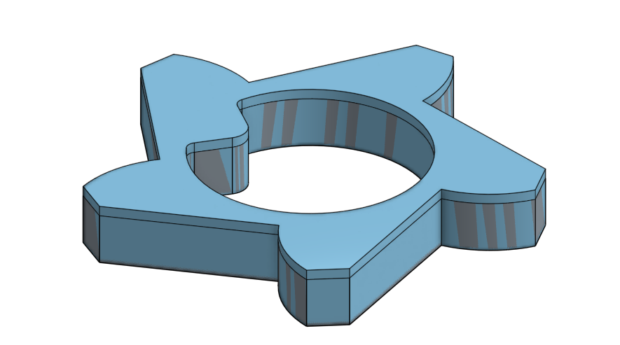
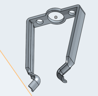
The tens-carry mechanism is the part of the Curta that most rewards being made large, and it is also the part with the highest repeat count — roughly fifteen carry levers, each with its bearing block and its own spring.
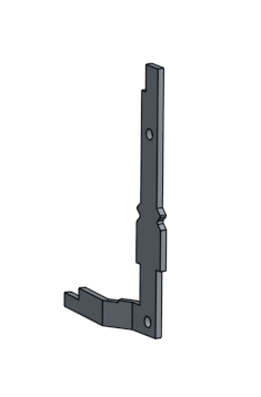
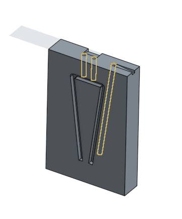
A repeated part is where a small modelling error becomes a large problem: get the lever wrong and it is wrong fifteen times, and every one of them must be reprinted. It is also where a parametric model earns its keep, since a single dimension change propagates to all of them.
2.6 When the drawings turned out to be wrong
The most instructive episode in the whole build is the discovery that the source material was not reliable.
Two separate errors surfaced. The main axle came out with its lower portion ninety degrees out of orientation, which Wu attributes to the engineering drawings being incorrect or mutually inconsistent, and corrected by adjusting the key orientation. And a dimensional discrepancy of roughly 0.4 mm was found between the scaled CAD and measurements taken from an actual Curta — resolved by consulting the real machine and correcting the model parametrically.
Two things follow from this. The first is practical: a scaled reproduction eventually needs access to an original to check against, because drawings of a machine that went through continuous revision over twenty-three years of production will not all describe the same machine. The second is a caution against a tempting assumption — that a surviving engineering drawing set constitutes a complete and self-consistent specification. For the Curta, at 3:1, it did not.
A third error was self-inflicted and equally costly: a step drum printed with its teeth misaligned by twenty degrees, requiring a complete reprint at thirteen hours each. At 3:1 the feedback loop on a modelling mistake is measured in half-days.
2.7 What the modelling phase established
By the end of it, three conclusions were fixed, and each shaped everything afterwards.
Printing at 4:1 had been the original plan; Wu moved to 3:1. His stated reservation about the larger scale was the fit problem — that parts would end up with either too much friction or too much wiggle room.
Tolerance, not geometry, was going to decide the project. His own summary is the line the next volume is built around: the tolerances between parts will be the defining factor in whether it works.
And the original’s engineering specifications exceeded what the available processes could hold, so the functional tolerances would have to be determined by experiment rather than read off a drawing.
Comments (0)