Arithmos · Volume 5
Arithmos — The Two-Digit Bench Test
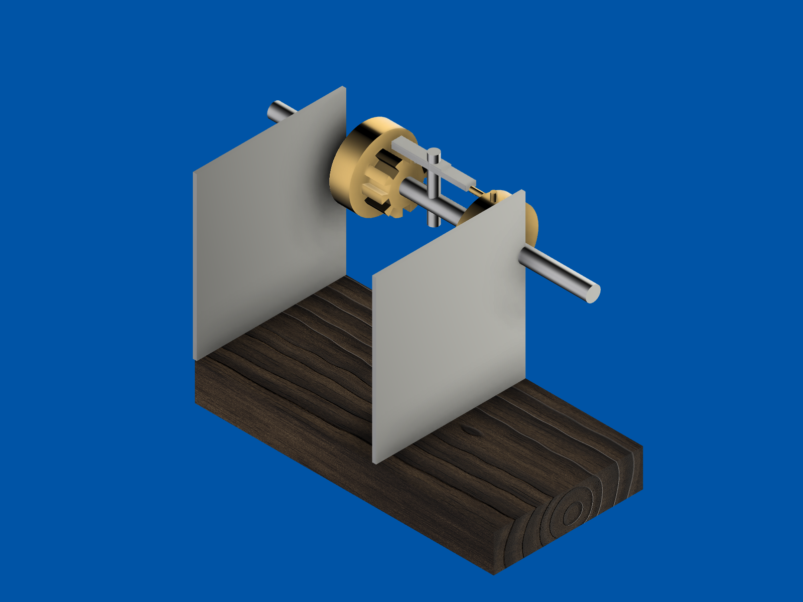
The carry mechanism was never modelled inside the machine. It was built as a separate document — a bench rig consisting of two drums, one shaft, a sautoir arm on a post, and a pinion, mounted on a walnut plank between two steel end plates. The rule attached to it is explicit: the main model’s carry placeholder is not to be touched until this rig has passed a hundred consecutive clean carries in printed plastic and again in brass.
03-outputs/).5.1 Version one, and the arm that could not reach
The first build placed eleven bodies: the walnut base, two end plates, two shafts, two brass drums, a pinion disc with teeth deferred, a carry pin, a pivot post, a sautoir arm, and a leaf spring. The specification called for a radial carry pin — a 2 mm rod projecting 3 mm out of the drum’s circumference at the position corresponding to the digit zero.
It did not work, and the reason was embarrassingly simple: the sautoir arm ran from x = -39 to x = -9, and the pin was at x = 0. The arm was eight millimetres short of the pin and could not catch it at any rotation of the drum. The rig was geometrically complete and kinematically impossible.
03-outputs/).5.2 Version 1.1: the finger goes axial
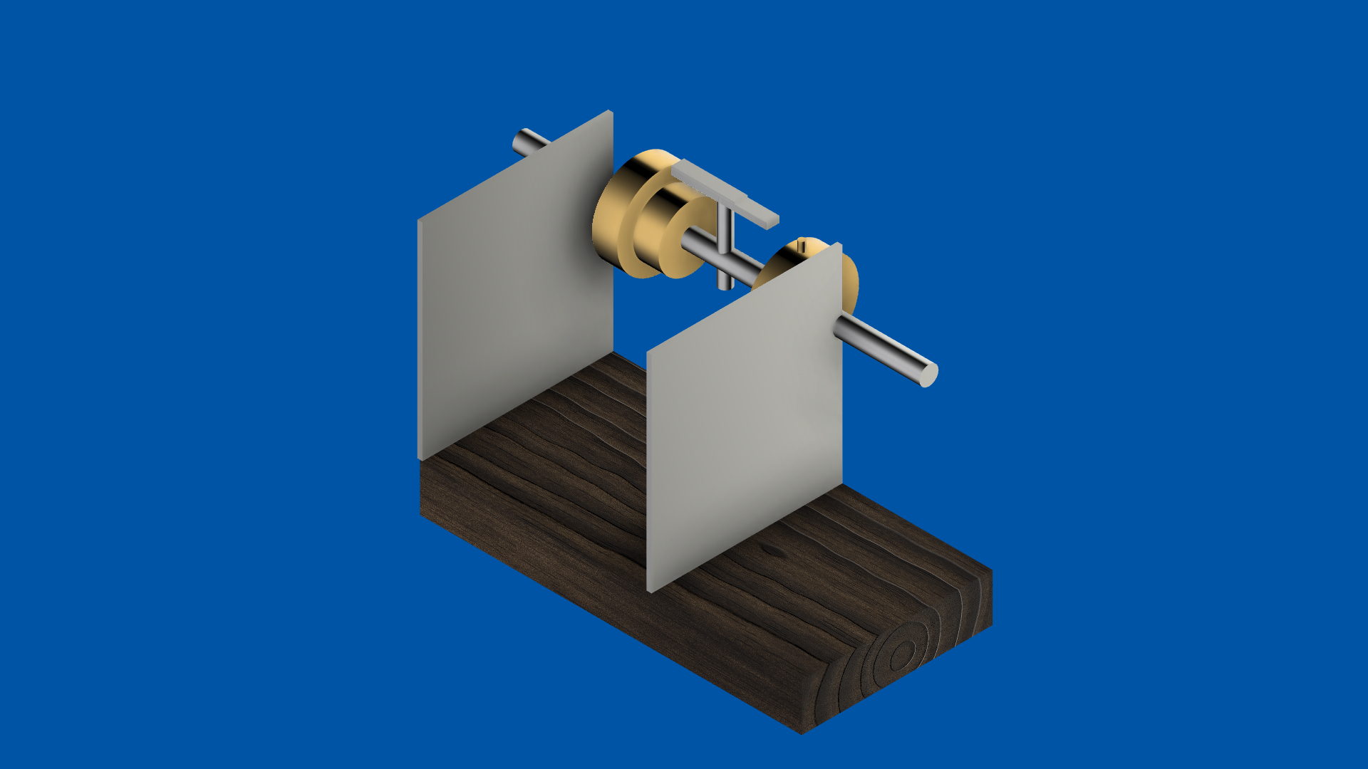
The fix was to stop borrowing from the wrong part of the ancestor. Pascal’s carry finger — the doigt — is not radial. It projects axially, out of the side face of the wheel, and sweeps a circle in the plane perpendicular to the shaft. The arm lies parallel to the shaft above it and is lifted from below as the finger comes round.
Version 1.1 deleted the units drum outright, rebuilt it clean, and joined a 2 mm by 5 mm brass finger to its face at a radius of 12 mm from the shaft axis. The sautoir arm and its leaf spring were both lowered four millimetres so that the arm’s underside sat in the finger’s sweep path. The rebuilt drum measured 4.6538 cubic centimetres.
Ten teeth were then cut into the pinion by the same rotate-cut-rotate pattern used on the register digits — a single rectangular cutter, positioned once, rotated 36 degrees between cuts. The first attempt failed silently because of the parameter bug described in volume four, cutting 0.091 cubic centimetres instead of 0.72. The corrected script produced a final volume of 1.5761 cubic centimetres, matching prediction, and a clean ten-tooth lantern pinion.
5.3 Version 1.2: the rig had been built around the wrong centre
The third round is the one worth reading, because it was found by looking at pictures rather than by running a check.
Screenshots taken for the animation made it obvious that the two end plates were not supporting anything. The shafts spanned x = -40 to +40. The left plate sat at x = -60, nineteen millimetres outboard of the shaft end, floating in space and touching nothing. The right plate sat at x = +12, leaving twenty-eight millimetres of shaft cantilevered past its only support. Both were moved so that their inner faces sit half a millimetre past the shaft ends.
Moving them exposed a worse problem. The original build had placed both shafts on the same axis — identical height and depth, differing only in where their centres sat along the axis. One ran from x = -40 to +40, the other from x = -88 to -8. They overlapped along thirty-two millimetres of the same line. Two solid steel rods had been modelled occupying the same space, and nothing had complained.
Separately, the tens drum at x = -52 now sat entirely outside the relocated left end plate. The whole tens-side assembly had been laid out as though the bench were centred on x = -24 rather than on zero.
The fix collapsed the problem rather than patching it. The redundant second shaft was deleted and both drums were journalled on the single remaining shaft, which already spanned the plates correctly. The tens drum and pinion were shifted twenty-eight millimetres inboard, and the pivot post, arm and spring fourteen millimetres, which happens to be consistent with the original Pascaline intent of two wheels on one arbor. The resulting drum spacing is twenty millimetres.
That last number deserves a note. The design document had specified forty-eight millimetres, widened from the main machine’s thirty, explicitly to give the sautoir room to swing. The rig as built is twenty — narrower than the main machine, and less than half the clearance the specification asked for. The fix script justifies it as roughly twelve millimetres between drum faces for a two-millimetre arm, which is a reasonable argument, but it is a different argument from the one in the design document, and the document was not updated.
5.4 Joints and the animation
With the layout settled, four joints were created: a revolute joint for each drum on the shaft, one for the pinion, and one for the sautoir arm on its pivot post. The static parts — base, end plates, shaft, pivot post, leaf spring — were locked together as a rigid group. A diagnostic script was needed along the way because the joint list initially returned nothing despite successful creation calls.
A six-frame animation was then driven through the joints and captured: at rest, approach, strike beginning, mid-strike, arm falling, and post-carry with the pinion advanced by 36 degrees.
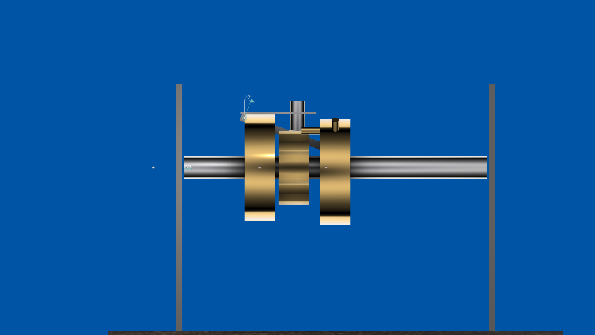
03-outputs/).The animation script is unusually honest about what this does and does not prove, and the caveat is worth quoting in substance: the joint system does not simulate contact. It poses each part at whatever value is set. Driving the arm to twenty degrees while the drum is at thirty-six is an assertion that the finger has lifted it, not a calculation that it did. The sequence is a visualisation of intent, not a validation of geometry. Volume six returns to this, because reading the numbers back against the as-built dimensions raises a question the animation cannot answer.
5.5 Ready to print, not yet printed
Ten parts were prepared for export — the eleventh disappeared with the deleted shaft — with each one tagged with both its eventual material and its bench-test material. The production intent is brass drums and pinion, stainless plates, shafts, post and arm, spring steel for the leaf, and walnut for the base. The bench version prints everything in PETG, with the leaf spring flagged as probably too compliant and marked for a music-wire replacement.
The whole set comes to about 174 kilobytes of mesh, which is a useful reminder of how small these parts are.
The export directory does not exist in the project tree. The manifest recording a successful run refers to Windows paths from before the project moved to Linux, and the export script that would recreate it has since been rewritten to write beside itself instead. In other words: the STLs were generated once, on another machine, and have not been regenerated here. Nothing has been sliced, nothing has been printed, and the hundred-cycle gate that the whole rig exists to satisfy has not been attempted.
Comments (0)