Arithmos · Volume 2
Arithmos — Drums, Digits and the Register
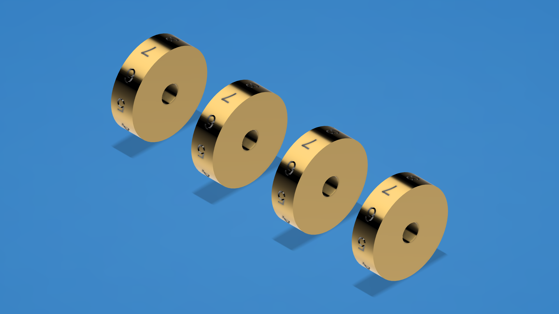
The register is the part of an adding machine the owner actually looks at, and on Arithmos it is four brass cylinders turning behind a slot. Each is 28 mm in diameter, 8 mm wide, bored 6 mm through the axis, and carries the digits zero to nine engraved around its circumference at 36-degree intervals. They sit at x = -45, -15, +15 and +45 mm on a common axis, 30 mm apart, with the slot cut across the front wall so that exactly one digit per drum is visible.
03-outputs/).2.1 Why the drums are cylinders and not discs
A pin-wheel calculator of the Odhner or Brunsviga type carries its numerals on the rim of a wheel that also does mechanical work. Arithmos separates the two jobs. The drums are pure display: they carry digits and nothing else, and they are driven from the shaft. That separation is what makes the register simple enough to be parametric — a drum is a bored cylinder with ten identical cuts in it, and changing the digit height or the cut depth means changing one constant and re-running a script.
It also means the drums are the one place in the machine where the finish matters more than the fit. A drum that is a tenth of a millimetre out of round still reads correctly through the slot. A carry arm a tenth of a millimetre out of position does not fire.
2.2 Cutting ten digits into a curved surface
The engraving is done by a pattern that recurs throughout the project and is worth naming: rotate, cut, rotate. A digit is sketched as text on a flat plane tangent to the drum, cut into the body by an extrusion scoped to that body alone, and then the drum is rotated by 36 degrees before the next digit is cut on the same fixed plane. After ten cuts the drum has turned a full circle and sits in its original orientation with ten evenly spaced recesses. The geometry never needs a cylindrical wrap; it needs one plane and a turntable.
The digits are 4 mm tall and cut 1 mm deep. That depth is a hard limit in the project notes rather than a preference: an early attempt used a much deeper cut and destroyed a drum outright, and the constant now carries a warning beside it. The glyph “1” is narrower than the rest and is offset by half a millimetre so that it sits centred in its window like the others.
Once cut, the recesses are darkened so the numerals read as black on brass. This is done by filtering faces rather than picking them — a face filter selects planar faces below half a square centimetre, and a second pass catches the curved recess walls, which the geometry kernel classifies differently. Between them the two passes find the 229 faces per drum that belong to the engraving and none of the large faces that belong to the cylinder or its ends.
2.3 The orientation problem, and why one rotation could not fix it
The most instructive failure in the register work was not mechanical. The digits came out upside down.
The first approach sketched the text on the plane tangent to the bottom of the drum, cut upward, and then rotated the drum by +90 degrees about the horizontal axis to bring that face to the front, followed by a 180-degree rotation to correct the reading direction. The digits arrived at the front face right-reading and upside down. Various further rotations were tried. None of them worked, and the reason they could not work is a fact about rigid motions rather than a bug: converting a right-reading, upside-down glyph into a right-reading, upright one requires a transform with determinant -1. That is a reflection, and no sequence of rotations produces one.
The fix was to move the cut rather than to add rotations. Engraving on the plane tangent to the top of the drum, cutting downward into it, and then applying a -90-degree rotation followed by a 180-degree rotation lands the glyphs upright and right-reading on the front face. It was verified on one rebuilt drum before being applied to the other three, and the script that performs it is kept in sync with the written recipe so the two cannot drift apart.
That episode is a small illustration of a general point: the cheapest way out of a geometry problem is often to change where you start, not to add another transform to the end.
2.4 Losing the digits, and getting them back
The engravings were lost once. A tidying pass through the model’s feature timeline deleted ninety-one features that the software reported as errored, on the assumption that an errored feature had produced nothing. That assumption is wrong. A feature flagged with an error retains the geometry it produced until the feature itself is deleted; deleting the feature removes the geometry with it. All four drums reverted to plain cylinders in one operation.
Recovery was possible only because the engraving was scripted. A recovery script reversed the two permanent rotations, re-ran the cutting recipe, and re-applied the rotations, returning every drum to 4.6623 cubic centimetres with upright digits. The blackening pass had to be re-run as well, and one drum needed a ten-minute timeout to complete it.
The lesson entered the project’s standing notes as a rule: before bulk-deleting features that report errors, suppress them first, which is reversible, and check the body’s physical properties to confirm no volume was lost.
2.5 Reading the result
The register slot began in the wrong place. It was originally cut at a height that put the drums’ forward tangent right at the bottom edge of the opening, so the visible digit was clipped. Raising the drums was not an option — they would have collided with the inside of the top wall. The slot was therefore re-cut lower, centred on the drum axis, and a clear acrylic panel fitted into its rabbet from inside.
The project notes still carry an optional item to lower the slot again for better digit visibility, which suggests the current position is workable rather than settled. Like most things in this project, it is a modelled judgement that has not yet met a printed part.
Comments (0)