Planimeters · Volume 4
Operating the 4242½: Step by Step, with Examples
This volume is a working manual for the K&E 4242½, built on K&E’s own Compensating Polar Planimeters (1949, 1957), the book the settings card in my case refers to. Every example uses my instrument’s own figures from that card:
Table 1 — This volume is a working manual for the K&E 4242½, built on K&E's own [Compensating Polar Planimeters](https://calculators.fubsypoly.com/library/ke-compensating-polar-planimeters-manual-1957/) (1949, 1957), the book the settings card in my case refers to. Every example uses my instrument's own figures from that card
| Setting | Value | Gives |
|---|---|---|
| tracer arm, English | 20.38 | 1 vernier unit = 0.01 sq in; 1 wheel turn = 10 sq in |
| tracer arm, metric | 31.52 | 1 vernier unit = 0.1 sq cm; 1 wheel turn = 100 sq cm |
| pole arm (with tracer arm 20.38) | 30.82 | neutral circle 200.00 sq in |
| pole arm (with tracer arm 31.52) | 33.76 (30.82 + 2.94) | neutral circle 2,000.0 sq cm |
Your own instrument’s card will have its own numbers; use those in place of mine. I have checked the arithmetic of every example.
4.1 Getting to know the instrument
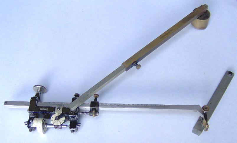
Take the tracer arm and carriage out of the case, holding them by the carriage, never by the measuring wheel. The instrument stands on three points: the measuring wheel’s rim, the guide wheel at the far end of the tracer arm, and the tracer point stop, a small foot beside the tracer point that holds the point just clear of the paper.
Hold the grip between thumb and second finger, with the forefinger on top ready to press the tracer point down. Adjust the stop so that the point only just clears the paper when you are not pressing it.
Now try what K&E’s manual suggests. Swing the carriage round the tracer point: the measuring wheel turns quickly and the dial slowly. Push it straight along the line of the tracer arm: the wheel slides without turning. That is how the instrument works (the theory volume explains why).
Never touch the rim of the measuring wheel. It is hardened steel with a matte surface that grips the paper, and the oil and acid of a fingerprint corrode it.
4.2 Setting the tracer arm
The carriage slides along the tracer arm and is held by two clamp screws, A and C, with a slow-motion screw, B, between them for fine adjustment (the manual’s figure 15). The scale on the tracer arm is in half-centimetres, read with a vernier on the carriage to a hundredth of a division. On the tracer arm, scale and vernier read from right to left.
To set the arm to 20.38:
- Loosen both clamp screws A and C.
- Slide the carriage until the vernier’s zero is near 20.4 on the arm.
- Tighten screw A only.
- Turn the slow-motion screw B until the vernier’s zero lies between 20.3 and 20.4 and its 8th line coincides exactly with a line on the arm scale: that is 20.38.
- Tighten screw C.
The card’s settings are the instrument’s own calibrated values, and they should be checked from time to time with the testing rule (section 10). K&E notes that each instrument has its own character, which can drift slightly with wear, and that the testing rule automatically takes care of it.
4.3 Setting the pole arm
For ordinary measurements, with the pole outside the figure, the pole arm length does not matter. K&E suggests making it at least three inches longer than the tracer arm, for smooth movement and the largest coverage. The pole arm’s own setting, 30.82 on my card, matters only for measuring with the pole inside a figure (section 8).
4.4 Setting up on the paper
- Use a flat, horizontal board. K&E warns against a sloping board: it reduces accuracy and the instrument may slide off; a dropped planimeter “will almost certainly be damaged”.
- The paper under the measuring wheel must be smooth, clean and uniform: no folds, tears, pinholes or creases. If the wheel has to cross onto another sheet, butt the edges together, with paper of the same thickness, and set the instrument up so the wheel rolls over the joint rather than sliding along it.
- Put the carriage a little to your right, the tracer arm at right angles to the front edge of the board, the tracer point towards you.
- Put the pole arm’s ball into its socket on the carriage, with the pole to the right and the arm roughly parallel to the front edge of the board.
- Press the pole needle firmly into the paper.
This is K&E’s “regular set-up”. Move the tracer about and note that it moves freely while the angle between the two arms stays between about 15° and 165°; keep it between 30° and 150° if you can. Twisting the grip can lift the guide wheel off the paper; if that happens during a measurement, start again.
The pole can go anywhere that lets the tracer reach the whole outline within those angles. There is no need to centre the figure on the pole.
4.5 Reading the dial, wheel and vernier
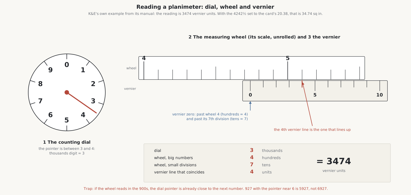
The reading is a four-figure number of vernier units (v.u.):
Table 2 — The reading is a four-figure number of vernier units (v.u.)
| Part | Gives | How |
|---|---|---|
| counting dial | thousands | the number the pointer has passed |
| measuring wheel, large numbers | hundreds | the number the vernier’s zero has passed |
| measuring wheel, small divisions | tens | how many small divisions past that number the vernier’s zero is |
| vernier | units | which vernier line lines up exactly with a wheel line |
The vernier has ten divisions in the space of nine on the wheel, so as the wheel moves one division its lines line up in turn: only one vernier line coincides with a wheel line at any time, and its number is the units figure.
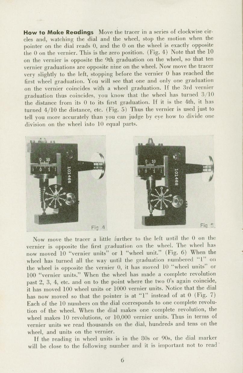
Find the zero position first: move the tracer in small clockwise circles until the dial pointer is on 0 and the wheel’s 0 is exactly opposite the vernier’s 0. Then move it slightly and watch: when the vernier’s 0 has moved one wheel division, the wheel has turned 10 v.u.; one large number is 100 v.u.; one full turn of the wheel is 1000 v.u. and moves the dial on by one; ten turns of the wheel take the dial once round, 10,000 v.u.
K&E’s example: the dial pointer is between 3 and 4; the vernier’s 0 is between 4 and 5 on the wheel, between the 7th and 8th small divisions; the 4th vernier line coincides. The reading is 3474.
The trap: when the wheel reads in the 900s, the dial’s pointer is already close to the next number. If the wheel and vernier read 927 and the pointer is near 6, the reading is 5927, not 6927. Always read the wheel first and then decide which number the dial has really passed.
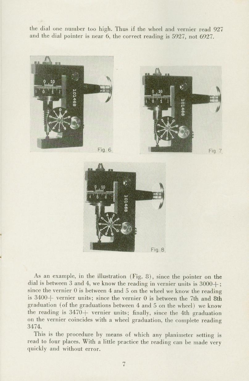
What a vernier unit is worth on my instrument:
Table 3 — What a vernier unit is worth on my instrument
| Tracer arm at 20.38 (English) | Tracer arm at 31.52 (metric) | |
|---|---|---|
| one vernier unit | 0.01 sq in | 0.1 sq cm |
| one small wheel division | 0.1 sq in | 1 sq cm |
| one large wheel number | 1 sq in | 10 sq cm |
| one wheel turn (one dial division) | 10 sq in | 100 sq cm |
| one dial revolution | 100 sq in | 1,000 sq cm |
4.6 Measuring an area, pole outside
- Mark a start. Draw a fine short line across the outline at a convenient point.
- Make a rough circuit first, to be sure the tracer can reach every part of the outline within the arm angles, and to get a feel for the speed. Where the tracer comes nearest the pole and the arms make a sharp angle, the wheel turns very fast: go slowly there.
- Take the first reading with the tracer point exactly on the start line. Write it down.
- Trace the outline clockwise, holding the grip as before, with your eye in line with the direction of motion and the point close to the paper. Do not use a straightedge to guide it along straight lines; it tends to add a cumulative error. Instead move your head so that the tracer travels straight towards or away from your eye. If the point wanders off the line, do not go back: move it as far the other way to compensate.
- Take the second reading with the tracer back exactly on the start line.
- Subtract the first reading from the second. If the dial’s 0 passed the pointer during the trace, add 10,000 to the second reading first.
- Repeat at least once as a check; for accurate work trace several times and average.
Example 1: a shape in square inches. Tracer arm at 20.38. First reading 3476; second reading 7491.
Table 4 — 6. Measuring an area, pole outside
| second reading | 7491 |
| first reading | 3476 |
| difference | 4015 v.u. |
| area (× 0.01 sq in) | 40.15 sq in |
Example 2: the dial passes zero. First reading 7452; second reading 2765. The dial went past 0, so add 10,000 to the second reading: 12,765 − 7452 = 5313 v.u. = 53.13 sq in.
Example 3: the same shape in metric. With the tracer arm at 31.52, a reading difference of 4015 would be 401.5 sq cm (× 0.1).
4.7 Areas to scale: maps and drawings
To read a map or scale drawing, multiply the area in square inches by a factor: the real area represented by one square inch of the drawing. A slide rule set to the factor converts every reading at once.
Example 4: a site plan at 1 in = 50 ft. One square inch on the plan represents 50 × 50 = 2,500 sq ft. A lot that measures 13.76 sq in on the plan is 13.76 × 2,500 = 34,400 sq ft.
Example 5: acres from a map at 1 in = 100 ft. One square inch represents 100 × 100 = 10,000 sq ft, and an acre is 43,560 sq ft, so the factor is 10,000 ÷ 43,560 = 0.2296 acre per sq in. A field measuring 21.05 sq in is 21.05 × 0.2296 = 4.83 acres.
Example 6: tracing several times. On a map at 1 in = 200 ft, one square inch is 40,000 sq ft. Trace the area four times without resetting and the factor for the total becomes 40,000 ÷ 4 = 10,000, a round number. If four circuits read 7.62 sq in in total, the area is 7.62 × 10,000 = 76,200 sq ft, and the averaging is done at the same time.
Example 7: a stretched map. K&E’s own example: a map nominally at 1 in = 200 ft has stretched 0.6% east–west and shrunk 0.2% north–south. One square inch then represents (200 ÷ 1.006) × (200 ÷ 0.998) = 198.8 × 200.4 = 39,840 sq ft, or 0.915 acre. Using that factor corrects the distortion.
K&E’s manual has tables of factors for the usual architectural and map scales (Table I for square inches, Table II for square centimetres).
4.7.1 Reading the scale directly
The tracer arm can be set so that the instrument reads the scale area directly, with no factor. Find the factor, then move its decimal point until it lies between 565 and 2032. That number is how many vernier units one circuit of the testing rule’s 10 sq in mark should read. The approximate tracer arm setting comes from K&E’s Table IV (English) or Table V (metric), or from the graph in figure 16; then the exact setting is found with the testing rule. A longer arm gives fewer vernier units per circuit, a shorter one more.
Example 8: a plan at 1 in = 30 ft, read directly. One square inch represents 30 × 30 = 900 sq ft, which is already within the range. Set the tracer arm to about 22.6, close to 20.38 × 1000 ÷ 900 = 22.64, and then adjust it with screw B until one circuit of the testing rule’s 10 sq in mark reads exactly 900 v.u. Ten square inches of plan, 9,000 sq ft of ground, now read 900 v.u., so each vernier unit is 10 sq ft. A lot that reads 2756 v.u. is 27,560 sq ft, or 27,560 ÷ 43,560 = 0.633 acre.
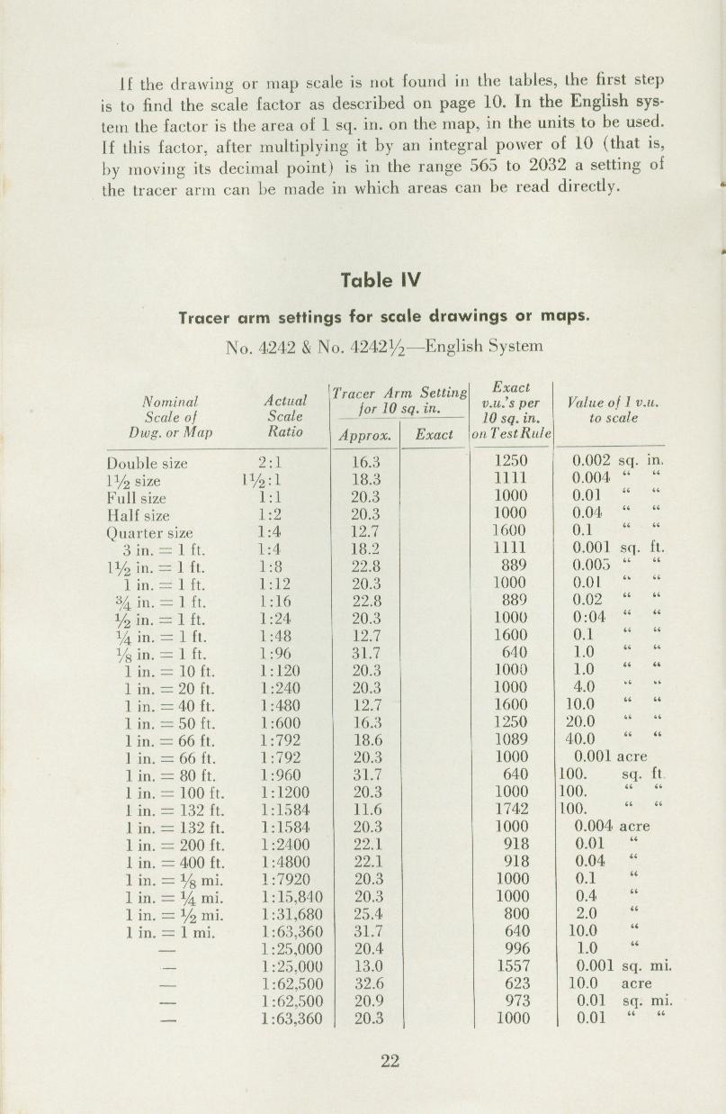
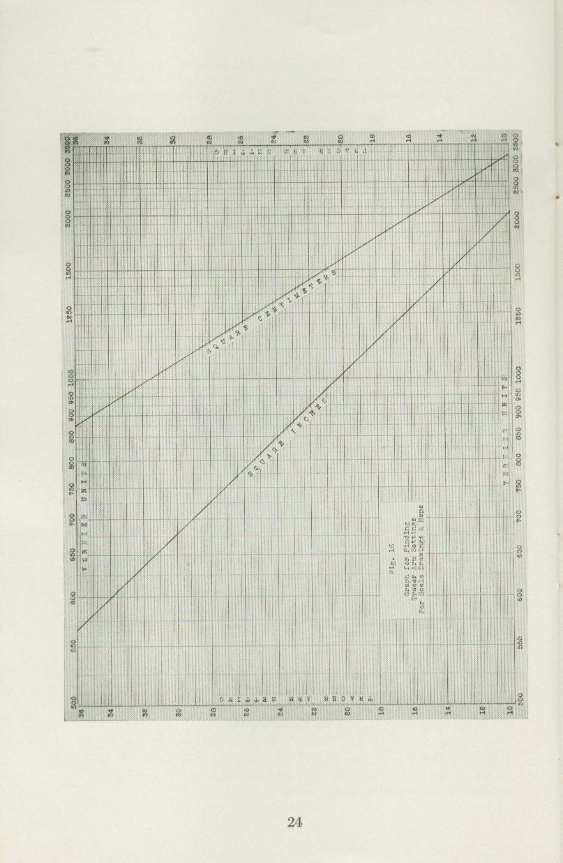
Short settings give the finest readings but limit the area; long settings cover more ground less precisely; settings near the middle of the arm are best for general use. If a factor falls outside the range, divide it by 2, 3 or 4 and multiply the readings by the same number: for a scale of 1:2.2 the factor is 4.84; 4840 ÷ 4 = 1210 lies in the range, so set for 1210 and multiply every reading by 4.
4.8 Large areas: the pole inside the figure
A figure too big to reach with the pole outside can be measured in pieces and added, which K&E recommends for two or three pieces. For larger figures, put the pole inside the figure, near its middle, and trace right round it. The figure must lie between a minimum and a maximum circle round the pole, so that the tracer can reach the whole outline.
With the pole inside, the reading is not the area itself but the difference between the area and the area of the neutral circle, C. With the pole arm at the card’s 30.82 and the tracer arm at 20.38, C = 200.00 sq in.
- Put the tracer on the start line and set the dial and wheel to 0000: lift the carriage slightly with the left forefinger and turn the wheel with your thumb (the manual’s figure 12). Never turn the wheel while it is touching the paper, and never touch its rim.
- Make a quick rough circuit, watching the dial, to see which way it goes and whether it makes more than one complete turn.
- Reset to 0000 and trace carefully clockwise. The final reading, in square inches, is W.
- Apply the case that matches what the dial did:
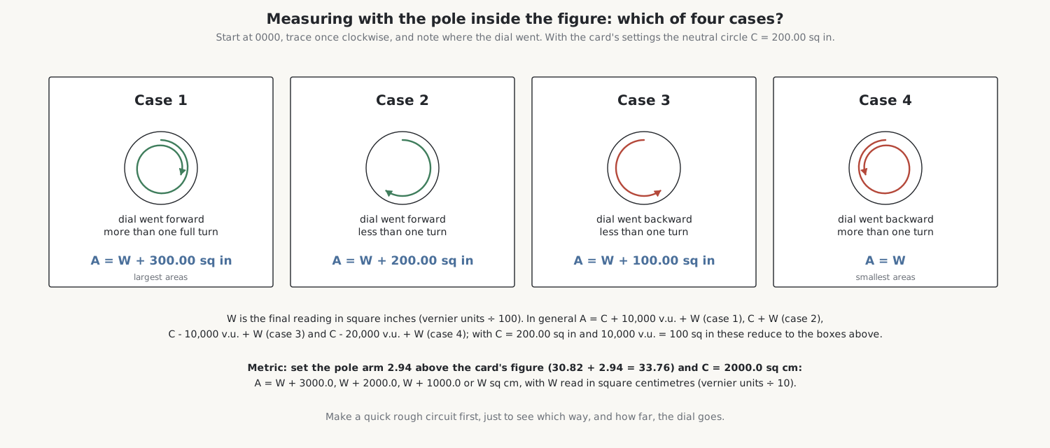
Table 5 — 8. Large areas: the pole inside the figure
| Case | The dial went | Area |
|---|---|---|
| 1 | forward, more than one full turn | A = W + 300.00 sq in |
| 2 | forward, less than one turn | A = W + 200.00 sq in |
| 3 | backward, less than one turn | A = W + 100.00 sq in |
| 4 | backward, more than one turn | A = W |
These come from K&E’s general formulas, A = C + 10,000 v.u. + W, C + W, C − 10,000 v.u. + W and C − 20,000 v.u. + W, with C = 200.00 sq in and 10,000 v.u. = 100 sq in.
Example 9: case 1. A large pond on a plan. The rough circuit moves the dial forward a little more than one full turn. The careful trace ends at 0642: W = 6.42 sq in. A = 6.42 + 300.00 = 306.42 sq in.
Example 10: case 2. The dial moves forward about seven divisions. The reading is 6852: W = 68.52 sq in. A = 68.52 + 200.00 = 268.52 sq in.
Example 11: case 3. The dial moves backward about six divisions, ending at 4164: W = 41.64 sq in. A = 41.64 + 100.00 = 141.64 sq in. (Check: the wheel ran backward 10,000 − 4164 = 5836 v.u., or 58.36 sq in, and 200.00 − 58.36 = 141.64.)
Example 12: case 4. A smaller figure; the dial goes backward a little more than one turn and ends at 9235: W = 92.35 sq in, and A = 92.35 sq in.
Metric. Set the tracer arm to 31.52 and the pole arm to 30.82 + 2.94 = 33.76; the neutral circle is then 2,000.0 sq cm, and the cases become A = W + 3000.0, W + 2000.0, W + 1000.0 and W sq cm, with W read in square centimetres (vernier units ÷ 10). Example 13: in case 2 a reading of 6852 is W = 685.2 sq cm, so A = 2,685.2 sq cm.
Checking the neutral circle. Draw a circle exactly 11.284 in across with a good compass: its area is 100.00 sq in. Trace it several times with the pole near its centre and average the readings. The dial will run backward, because the circle is smaller than the neutral circle. The neutral circle is the known area minus the reading: if the trace runs backward 100.00 sq in, C = 100.00 − (−100.00) = 200.00 sq in. K&E’s manual (p. 28) gives the case formulas for this check.
For extra-large areas the pole arm can be lengthened to give a larger neutral circle; K&E’s manual (pages 26–27) shows how to work out the pole arm length for any neutral circle from r = √(C/π − l² − 2al), with a = 1.151 in, measuring the arm with a scale from the centre of the ball to the pole needle.
4.9 Indicator diagrams: mean effective pressure
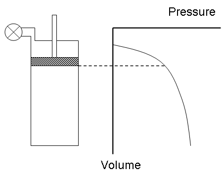
A steam-engine (or compressor) indicator card is a closed loop of pressure against stroke. Its mean effective pressure (MEP) is the area of the loop divided by its length, times the scale of the indicator spring.
The general method, which works on any planimeter:
- Find the factor: the pressure scale divided by the length of the diagram.
- Measure the area of the diagram.
- Multiply.
Example 14. The indicator spring scale is 80 lb/sq in per inch and the diagram is 4 inches long: the factor is 80 ÷ 4 = 20. The loop measures 2.31 sq in. The MEP is 2.31 × 20 = 46.2 lb/sq in.
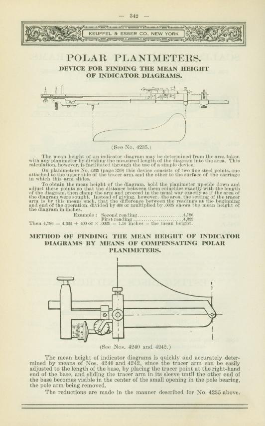
The direct method of the 4242. The 4242’s wheel is made so that its circumference is exactly 2.5 inches, which gives a direct reading of the mean height. Square off the diagram with fine pencil lines; set the carriage over one end and slide the tracer arm until its length equals the length of the diagram; clamp A and C; trace the diagram. The instrument then reads the mean height at 400 v.u. per inch, and
MEP = (area in v.u. × pressure scale) ÷ 400
Example 15 (K&E’s): the pressure scale is 80 lb/sq in per inch and the traced area reads 355 v.u. MEP = 355 × 80 ÷ 400 = 71.0 lb/sq in.
K&E’s 1936 catalogue says the 1930s 4242½ was sold “without provision for finding the mean height of indicator diagrams”, while the 1957 manual says its 4242 chapter applies to the 4242½ too. The direct method needs only that the tracer arm can be set to the diagram’s length, so it should work within the arm’s range; check it on a rectangle of known size first. The general method always works.
Circular charts. For a circular recorder chart, K&E suggests measuring the area A inside the curve and finding the mean radius r = √(A/π) = 0.5642 √A; the reading at that radius on the chart is the mean value. K&E’s 4215 radial planimeter does this job better.
4.10 Testing and adjusting with the testing rule
The testing rule makes the tracer point go round a circle of exactly known area, so the instrument can be checked and its tracer arm set exactly.
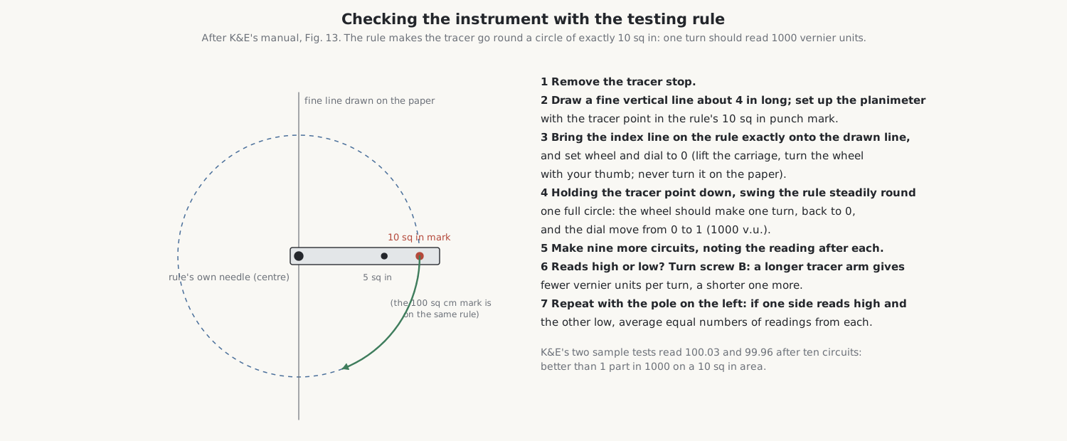
- Remove the tracer stop.
- Draw a fine straight line about 4 inches long on the paper. Set up the planimeter in the regular way, put the testing rule’s needle in the paper, and put the tracer point in the rule’s 10 sq in punch mark.
- Bring the index line on the rule exactly onto the drawn line, and set the wheel and dial to 0 (lifting the carriage, as in section 8).
- Holding the tracer point down firmly in its mark, swing the rule round one complete circle at a moderate, even speed, back to the line. The wheel should make exactly one turn, back to 0, and the dial move from 0 to 1: 1000 v.u., or 10.00 sq in.
- Make nine more circuits, writing down the reading after each.
- If the instrument reads high or low, adjust the tracer arm with screw B (loosen C first, retighten it after): lengthening the arm gives fewer vernier units per circuit, shortening it more. Repeat until it reads true. Note the new setting.
- Repeat the test with the pole set up on the left instead of the right, and tracing anticlockwise. If the instrument reads high one way and low the other, take equal numbers of readings in each position and average them: this is the “compensating” use that gives the instrument its name.
For the metric setting, use the 100 sq cm mark: one circuit should read 1000 v.u. at 0.1 sq cm each. For very short tracer arm settings, below 14, use the 5 sq in mark and multiply the reading by 3.1 to compare with 100 sq cm.
K&E’s manual prints two typical tests of ten circuits. The first read 10.02, 20.02, 30.02 … 100.03: a small error in the starting setting, and otherwise accurate to the limit of reading the vernier. The second read 10.00, 20.00, 29.99 … 99.96: a slight tendency to read low, about 1 part in 2,500. Both show a precision better than 1 in 1,000 on a 10 sq in area.
4.11 How accurate is it?
K&E lists four things that decide accuracy.
- The instrument’s condition, checked with the testing rule.
- The conditions: the paper surface above all (no folds, pinholes or waves; its texture matters less than its uniformity), a level board, and temperature. K&E calibrated its instruments to read correctly at 70 °F.
- The operator: good eyesight, a steady hand, patience, good light and a comfortable position. In K&E’s test two operators traced the same figure ten times each; both averaged 12.88 sq in, agreeing to 1 part in 1,500, but one operator’s average deviation was nearly twice the other’s.
- The size of the figure. Tracing 0.01 inch outside the line round a 1 inch square adds 4% to its area; round a 10 inch square it adds only 0.4%. For similar figures the error falls roughly as the square root of the area, so a 1 sq in figure can be measured only to about 1 in 316 if a 10 sq in one is good to 1 in 1,000. As a rule, the percentage error is about 100 × perimeter × tracing error ÷ area.
With repeated careful measurements under good conditions, K&E claimed 1 part in 1,000 for areas over 10 square inches.
4.12 A summary card
- Level board, smooth paper, pole to the right, arms between 30° and 150°.
- Tracer arm 20.38 for square inches (31.52 for square centimetres); clamp A, fine-set with B, clamp C.
- Mark a start line; read; trace clockwise; read; subtract (add 10,000 if the dial passed 0).
- Vernier units × 0.01 = square inches (× 0.1 = square centimetres).
- Trace twice or more, and average; for best results average pole-left and pole-right.
- Pole inside: start at 0000; rough circuit first; then W + 300, + 200, + 100 or + 0 sq in.
- Check with the testing rule: one circuit of the 10 sq in mark = 1000 v.u.
Comments (0)